Monitoring tissue temperature while using an irrigated catheter

a technology of irrigated catheters and tissue temperature, which is applied in the field of measuring can solve problems such as unwanted increase of the temperature of the tissu

Active Publication Date: 2011-09-15
BIOSENSE WEBSTER (ISRAEL) LTD
View PDF11 Cites 69 Cited by
  • Summary
  • Abstract
  • Description
  • Claims
  • Application Information

AI Technical Summary

Benefits of technology

[0037]compare the first and second estimated geometrical vectors to formulate an optimal geometric vector, and
[0038]estimate a temperature of the tissue using the optimal geometric vector.

Problems solved by technology

The application of the ablation energy to body tissue, if uncontrolled, may lead to an unwanted increase of temperature of the tissue.

Method used


Image

  • Monitoring tissue temperature while using an irrigated catheter
  • Monitoring tissue temperature while using an irrigated catheter
  • Monitoring tissue temperature while using an irrigated catheter

Examples


Embodiment Construction

Overview

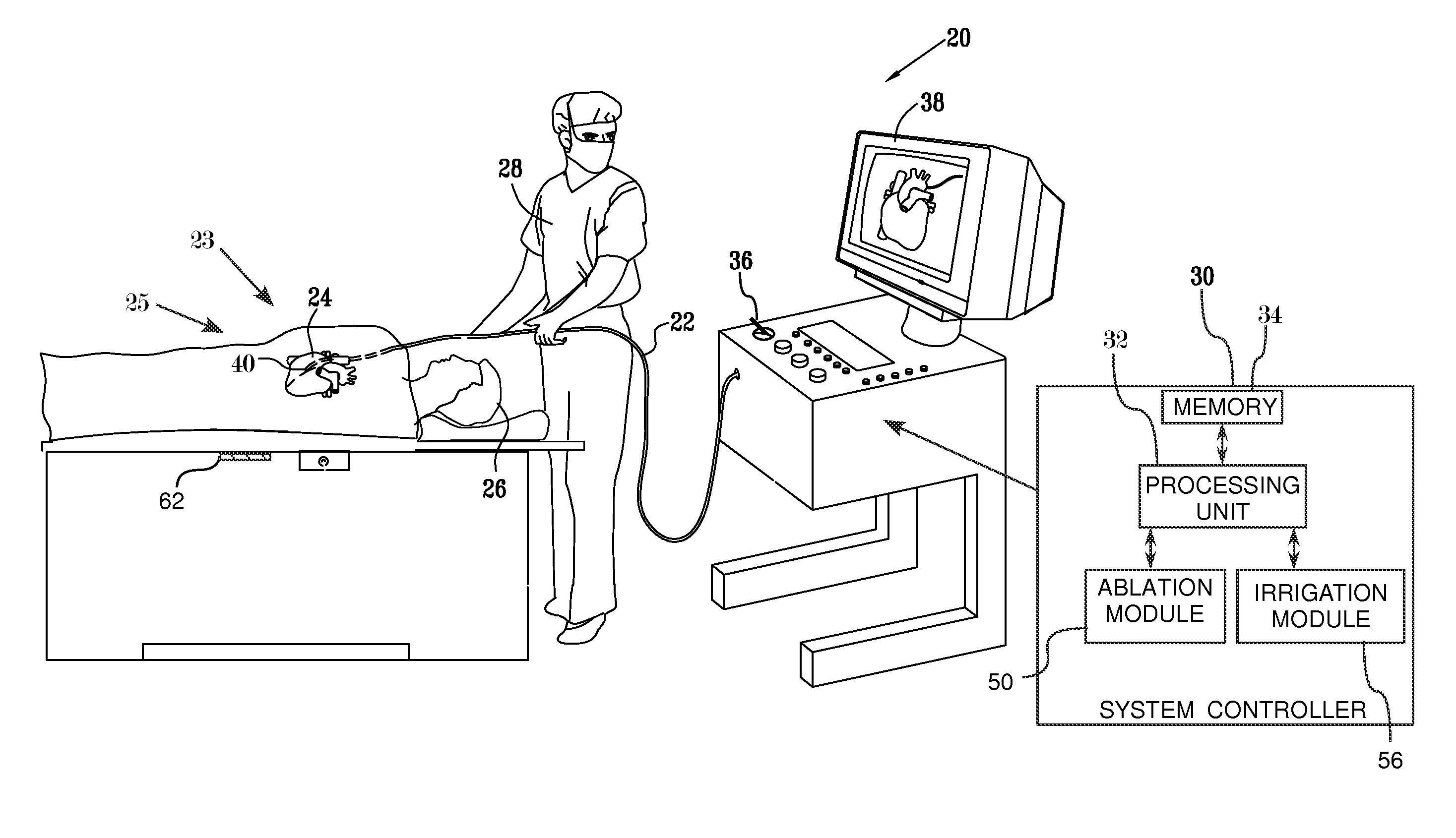
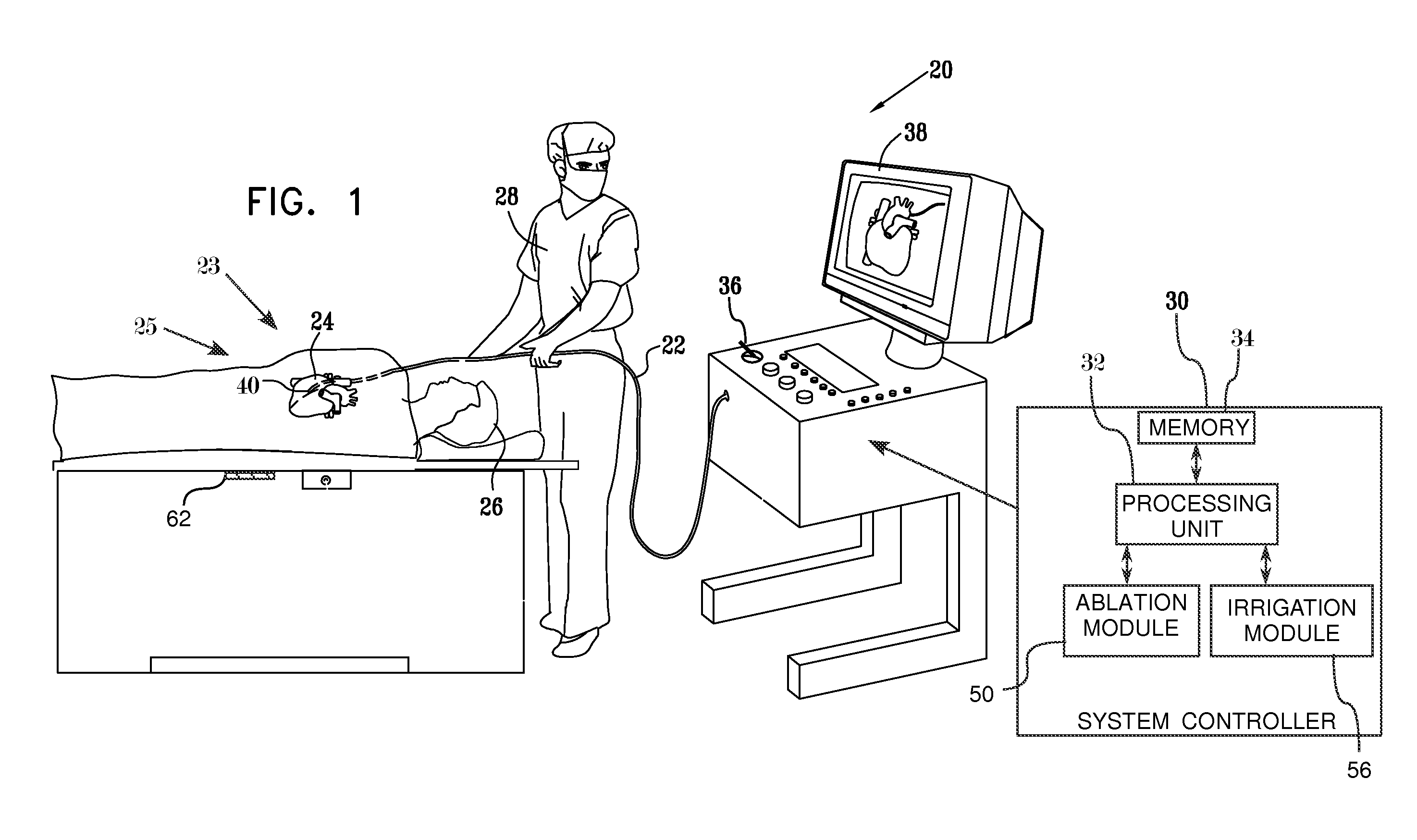
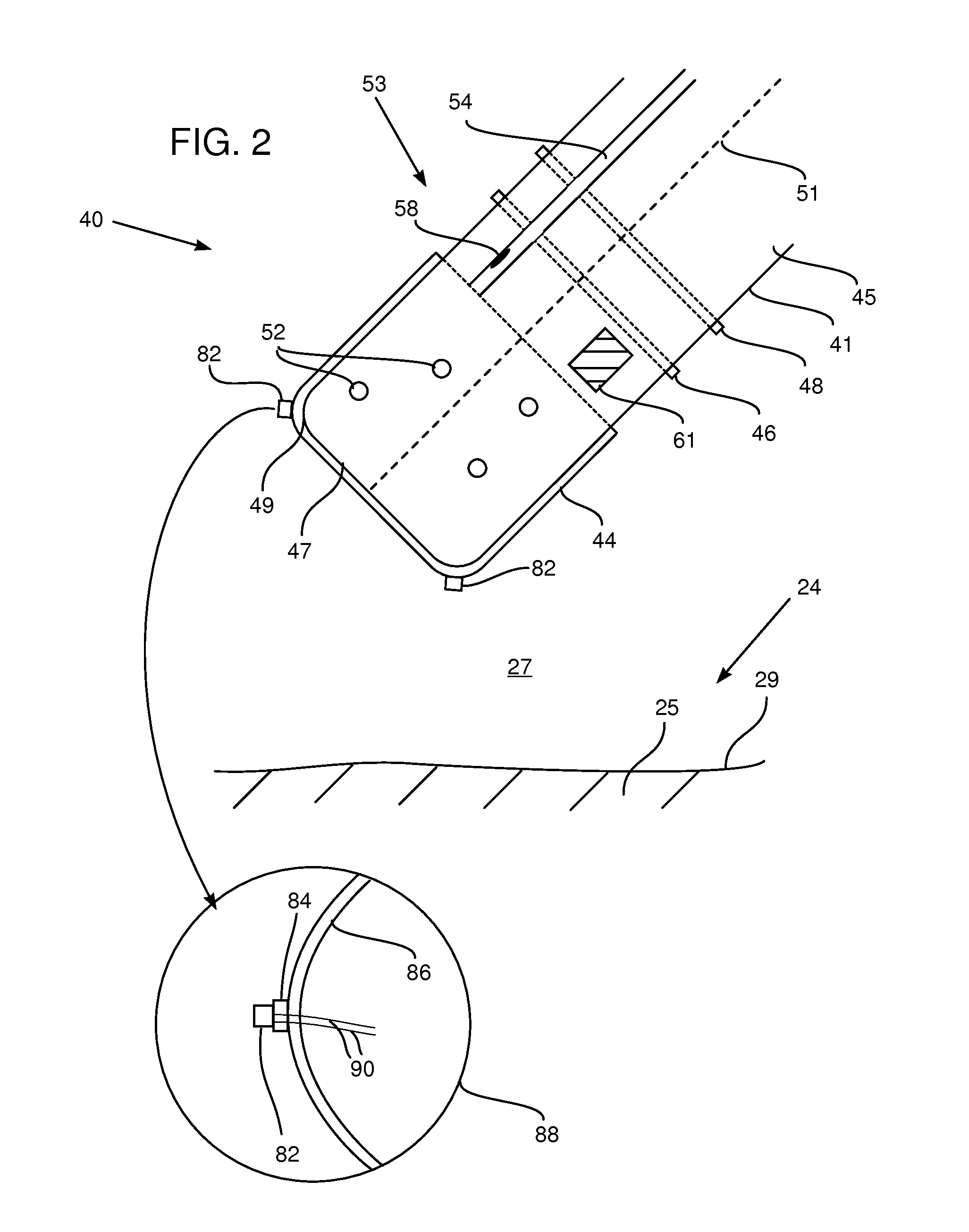
[0084]An embodiment of the present invention uses a mathematical model of physical parameters related to an ablation procedure. The modeled parameters represent the distal tip of a probe in proximity to body tissue during the procedure, which is performed by the probe. The ablation procedure consists of an ablation stage, in which power is applied to the body tissue at a level sufficient to ablate the tissue, and a non-ablation stage in which the power level is reduced so that no tissue ablation occurs. Typically, the period of the non-ablation stage is brief in comparison with the period of the ablation stage. During the ablation stage, a subgroup of the physical parameters is measured, generating ablative values of the subgroup. During the non-ablation stage, the subgroup of parameters is measured to generate non-ablative values of the subgroup.

[0085]The model is used to calculate ablative values of the subgroup for the ablation stage, and non-ablative values for the non-a...


PUM


Abstract

Apparatus, consisting of a probe, configured to be inserted into a body cavity, and an electrode having an outer surface and an inner surface connected to the probe. The apparatus also includes a temperature sensor, protruding from the outer surface of the electrode, which is configured to measure a temperature of the body cavity.

Description

CROSS-REFERENCE TO RELATED APPLICATION[0001]This application is a continuation-in-part of U.S. patent application Ser. No. 13 / 036,469, filed Feb. 28, 2011, which is incorporated herein by reference.FIELD OF THE INVENTION[0002]The present invention relates generally to ablation of body tissue, and specifically to measuring the temperature of the tissue during the ablation.BACKGROUND OF THE INVENTION[0003]Medical procedures involving ablation of the heart may be used to cure a variety of cardiac arrhythmia, as well as to manage atrial fibrillation. Such procedures are known in the art. Other medical procedures using ablation of body tissue, such as treating varicose veins, are also known in the art. The ablation energy for these procedures may be in the form of radio-frequency (RF) energy.[0004]The application of the ablation energy to body tissue, if uncontrolled, may lead to an unwanted increase of temperature of the tissue. It is consequently important to measure the temperature of...

Claims


Application Information

Patent Timeline
Patent Type & Authority Applications(United States)
IPC IPC(8): A61B5/01
CPCA61B5/01A61B18/1492A61B2017/00084A61B2019/5251A61B2019/467A61B2019/502A61B2019/504A61B2019/461A61B2034/102A61B2034/104A61B2034/2051A61B2090/061A61B2090/067
Inventor BAR-TAL, MEIRBERGER, ABRAHAMHAZAN, AVRIOSADCHY, DANIEL
Owner BIOSENSE WEBSTER (ISRAEL) LTD
Why Eureka
Try Eureka