
Tubular severing system and method of using same

a tubular severing and tubular technology, applied in the direction of fluid removal, sealing/packing, borehole/well accessories, etc., can solve the problem that the leakage of subsurface fluids may pose a significant environmental threa

Active Publication Date: 2011-09-22
NAT OILWELL VARCO LP
View PDF27 Cites 17 Cited by
  • Summary
  • Abstract
  • Description
  • Claims
  • Application Information

AI Technical Summary

Problems solved by technology

Leakage of subsurface fluids may pose a significant environmental threat if released from the wellbore.

Method used


Image

  • Tubular severing system and method of using same
  • Tubular severing system and method of using same
  • Tubular severing system and method of using same

Examples


Embodiment Construction

[0035]The description that follows includes exemplary apparatus, methods, techniques, and / or instruction sequences that embody techniques of the present inventive subject matter. However, it is understood that the described embodiments may be practiced without these specific details.

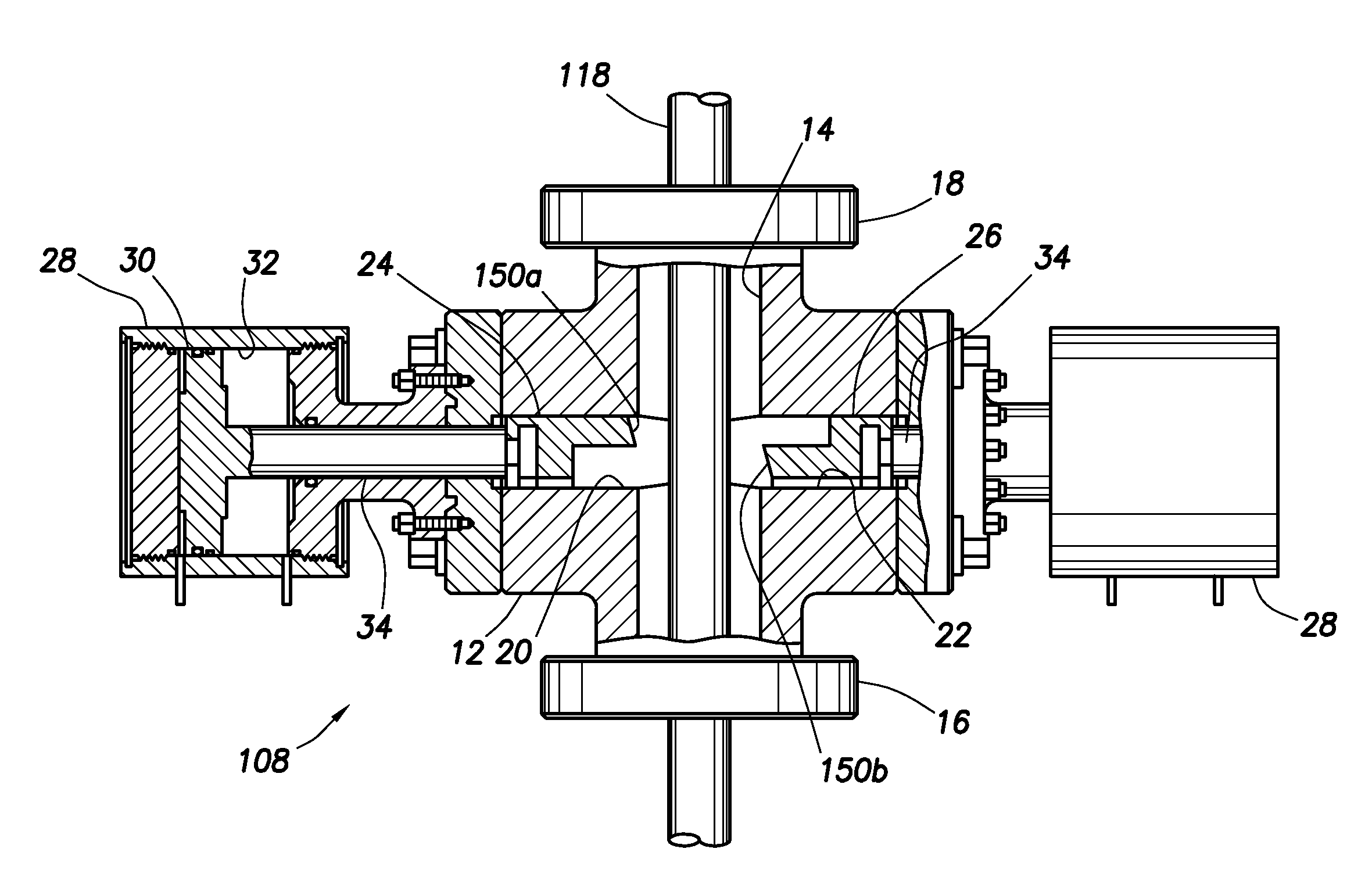
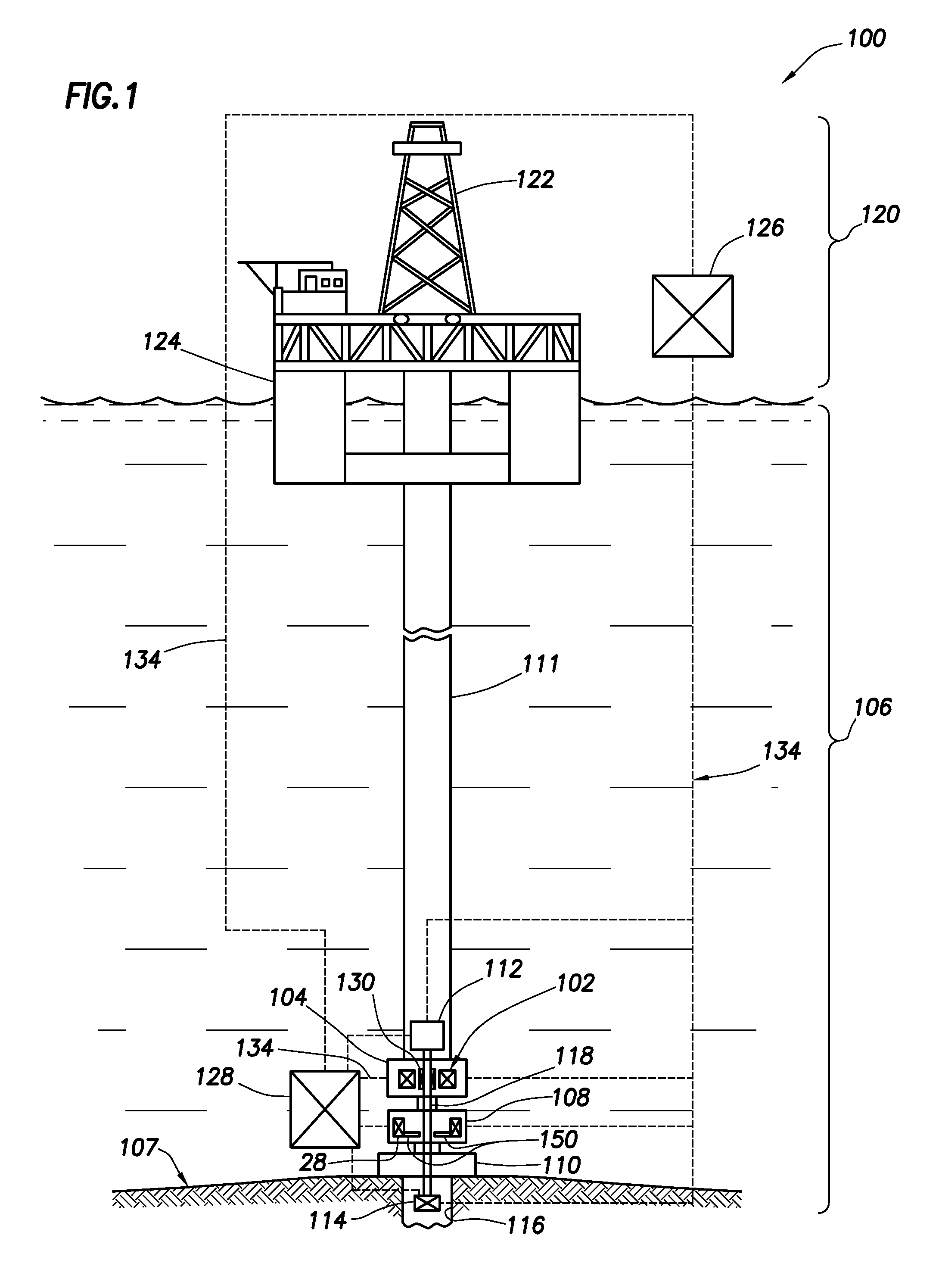
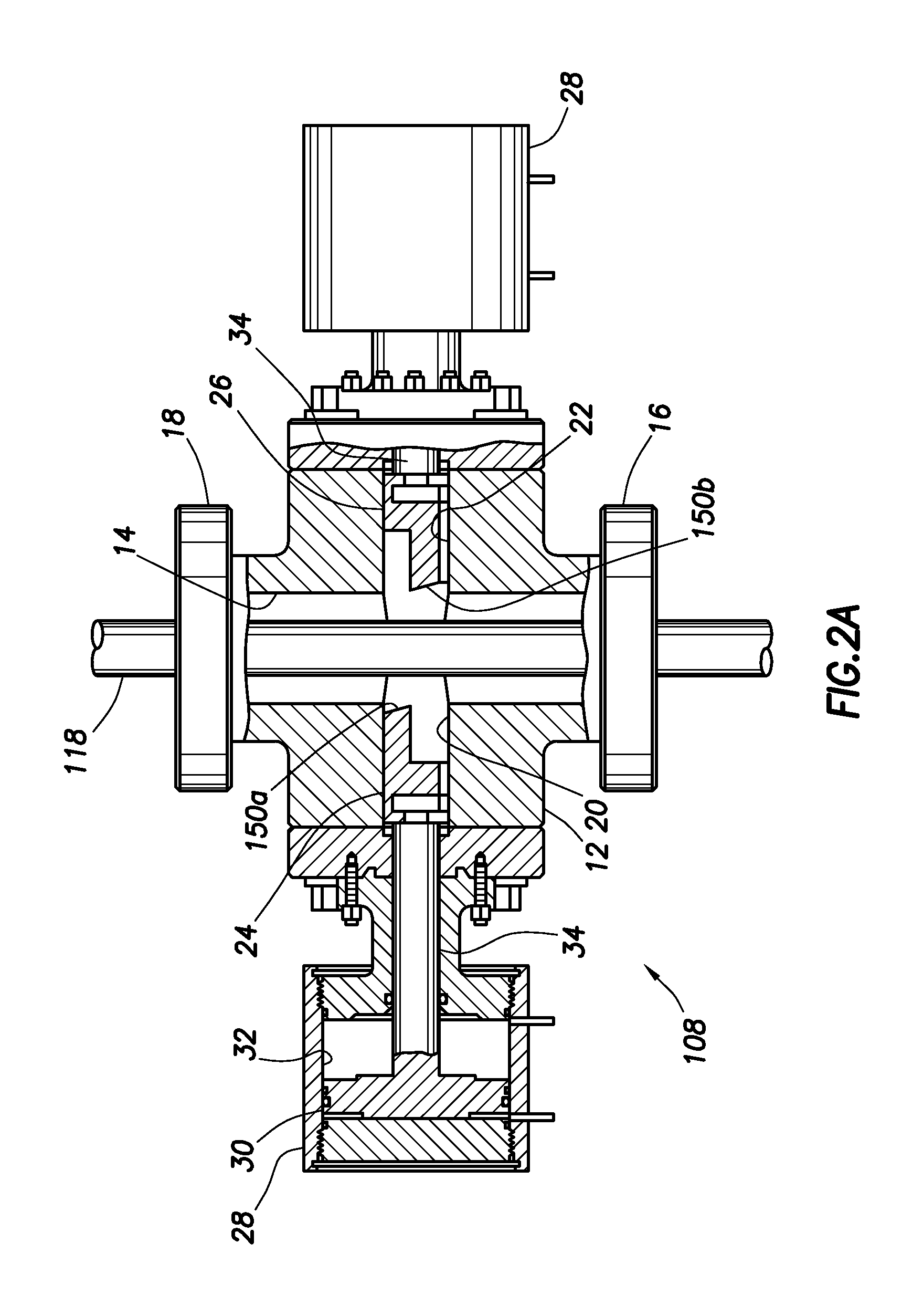
[0036]This application relates to a BOP and at least one blade used to sever a tubular at a wellsite. The tubular may be, for example, a tubular that is run through the BOP during wellsite operations. The severing operation may allow the tubular to be removed from the BOP and / or the wellhead. Severing the tubular may be performed, for example, in order to seal off a borehole in the event the borehole has experienced a leak, and / or a blow out.

[0037]The BOP is provided with various blade configurations for facilitating severance of the tubular. These blades may be configured with piercing points, cutting surfaces and / or shavers intended to reduce the force required to sever a tubular. The invention provide...


PUM


Abstract

Techniques for severing a tubular of a wellbore penetrating a subterranean formation are provided. A blade is extendable by a ram of a blowout preventer positionable about the tubular. The blade includes a blade body having a front face on a side thereof facing the tubular. At least a portion of the front face has a vertical surface and at least a portion of the front face has an inclined surface. The vertical surface is perpendicular to a bottom surface of the blade body. The blade body includes a loading surface on an opposite side of the blade body to the front face. The loading surface is receivable by the ram. The blade also includes a cutting surface along at least a portion of the front face for engagement with the tubular, and a piercing point along the front face for piercing the tubular. The piercing point has a tip extending a distance from the cutting surface.

Description

CROSS-REFERENCE TO RELATED APPLICATIONS[0001]This application is a continuation-in-part of U.S. Non-Provisional application Ser. No. 12 / 883,469 filed on Sep. 16, 2010, which is a continuation of U.S. Non-Provisional application Ser. No. 12 / 151,279 filed on May 5, 2008, which is now U.S. Pat. No. 7,814,979, which is a divisional of U.S. Non-Provisional application Ser. No. 11 / 411,203 filed on Apr. 25, 2006, which is now U.S. Pat. No. 7,367,396, the entire contents of which are hereby incorporated by reference. This application also claims the benefit of U.S. Provisional Application No. 61 / 349,660 on May 28, 2010, U.S. Provisional Application No. 61 / 349,604 filed on May 28, 2010, U.S. Provisional Application No. 61 / 359,746 filed on Jun. 29, 2010, and U.S. Provisional Application No. 61 / 373,734 filed on Aug. 13, 2010, the entire contents of which are hereby incorporated by reference.BACKGROUND OF THE INVENTION[0002]1. Field of the Invention[0003]This present invention relates generally...

Claims


Application Information

Patent Timeline
Patent Type & Authority Applications(United States)
IPC IPC(8): E21B29/08E21B33/06
CPCE21B33/063
Inventor SPRINGETT, FRANK BENJAMINJOHNSON, CHRISTOPHER DALEPETERS, SHERN EUGENEENSLEY, ERIC TREVOR
Owner NAT OILWELL VARCO LP
Learn More