Power systems for driving light emitting diodes and associated methods of control

a technology of power system and driving light, which is applied in the direction of electroluminescent light source, electric lighting source, and use of semiconductors. it can solve the problems of ccfls that have a relatively short life, are not environmentally friendly, and variable luminance of led backlight system, and damage some leds

Active Publication Date: 2011-09-22
MONOLITHIC POWER SYST
View PDF4 Cites 53 Cited by
  • Summary
  • Abstract
  • Description
  • Claims
  • Application Information

AI Technical Summary

Problems solved by technology

The CCFLs have a relatively short lifetime and are not environmentally friendly, and LEDs have been steadily replacing CCFLs as backlight sources.
However, the resistance of a particular LED may be different than others,

Method used


Image

  • Power systems for driving light emitting diodes and associated methods of control
  • Power systems for driving light emitting diodes and associated methods of control
  • Power systems for driving light emitting diodes and associated methods of control

Examples


Embodiment Construction

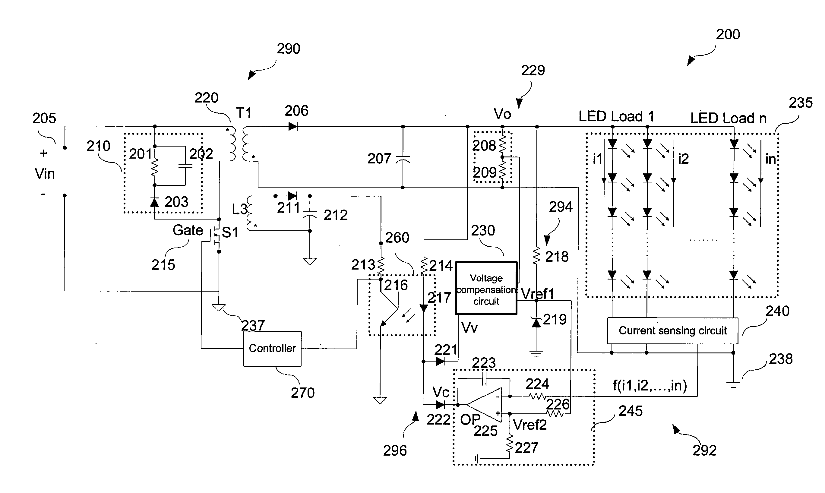
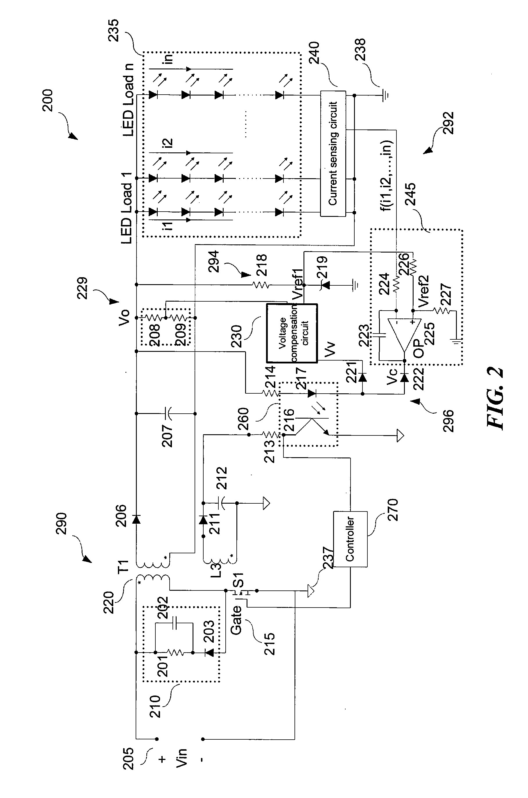
ically illustrates a voltage compensation circuit according to one embodiment of the present technology.

[0011]FIG. 7 schematically illustrates another voltage compensation circuit according to one embodiment of the present technology.

DETAILED DESCRIPTION

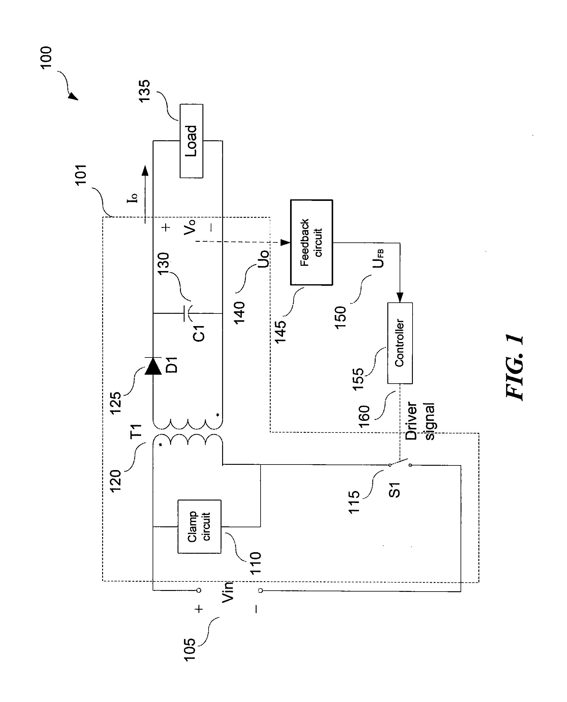
[0012]Various embodiments of LED power systems, driver circuits, and methods of control are described below. Many of the details, dimensions, angles, shapes, and other features shown in the figures are merely illustrative of particular embodiments of the technology. As used herein, the phrase an “LED load” generally refers to one LED device, a plurality of LEDs, one LED string, a plurality of LED strings, an LED array, a plurality of LED arrays, and / or other types of LED components with suitable configurations. A person skilled in the relevant art will also understand that the technology may have additional embodiments, and that the technology may be practiced without several of the details of the embodiments described below with ref...


PUM


Abstract

Embodiments of LED driver circuits and the associated methods are disclosed herein. In one embodiment, the LED driver circuit comprises a switch-mode converter, a controller, a feedback circuit, and a gating circuit. The feedback circuit includes a current balance circuit. The gating circuit is responsive to both a current feedback signal and a voltage feedback signal and is configured to select one of them as the feedback signal.

Description

CROSS-REFERENCE TO RELATED APPLICATION(S)[0001]This application claims priority to Chinese Patent Application No. 201010124649.6, filed Mar. 16, 2010, the disclosure of which is incorporated herein by reference in its entirety.TECHNICAL FIELD[0002]The present technology relates to power systems for driving light emitting diodes (LEDs) and associated methods of control.BACKGROUND[0003]LEDs are a type of solid state semiconductor devices capable of converting electrical power into visible light. The application of LEDs primarily comprises LED backlight, LED illumination, and LED display. Currently, cold cathode fluorescent lamps (“CCFLs”) are used as a light source in most liquid crystal displays (“LCDs”). The CCFLs have a relatively short lifetime and are not environmentally friendly, and LEDs have been steadily replacing CCFLs as backlight sources.[0004]An LED backlight system commonly includes strings of serially coupled LEDs and a corresponding LED driver circuit. A relative high ...

Claims


Application Information

Patent Timeline
IPC IPC(8): H05B37/02H05B44/00
CPCH05B33/0809Y02B20/341H05B33/0827H05B33/0812H05B45/395H05B45/46Y02B20/30H05B45/385
Inventor HU, JINDU, LEIREN, YUANCHENGZHANG, JUNMINGYE, ZHIJUN
Owner MONOLITHIC POWER SYST
Why Eureka
Try Eureka