

Power conversion apparatus
a power conversion and apparatus technology, applied in the direction of electrical apparatus, capacitors, fixed capacitor housing/encapsulation, etc., can solve problems such as skin effect hea
- Summary
- Abstract
- Description
- Claims
- Application Information
AI Technical Summary
Benefits of technology
Problems solved by technology
Method used
Image

Examples
first embodiment
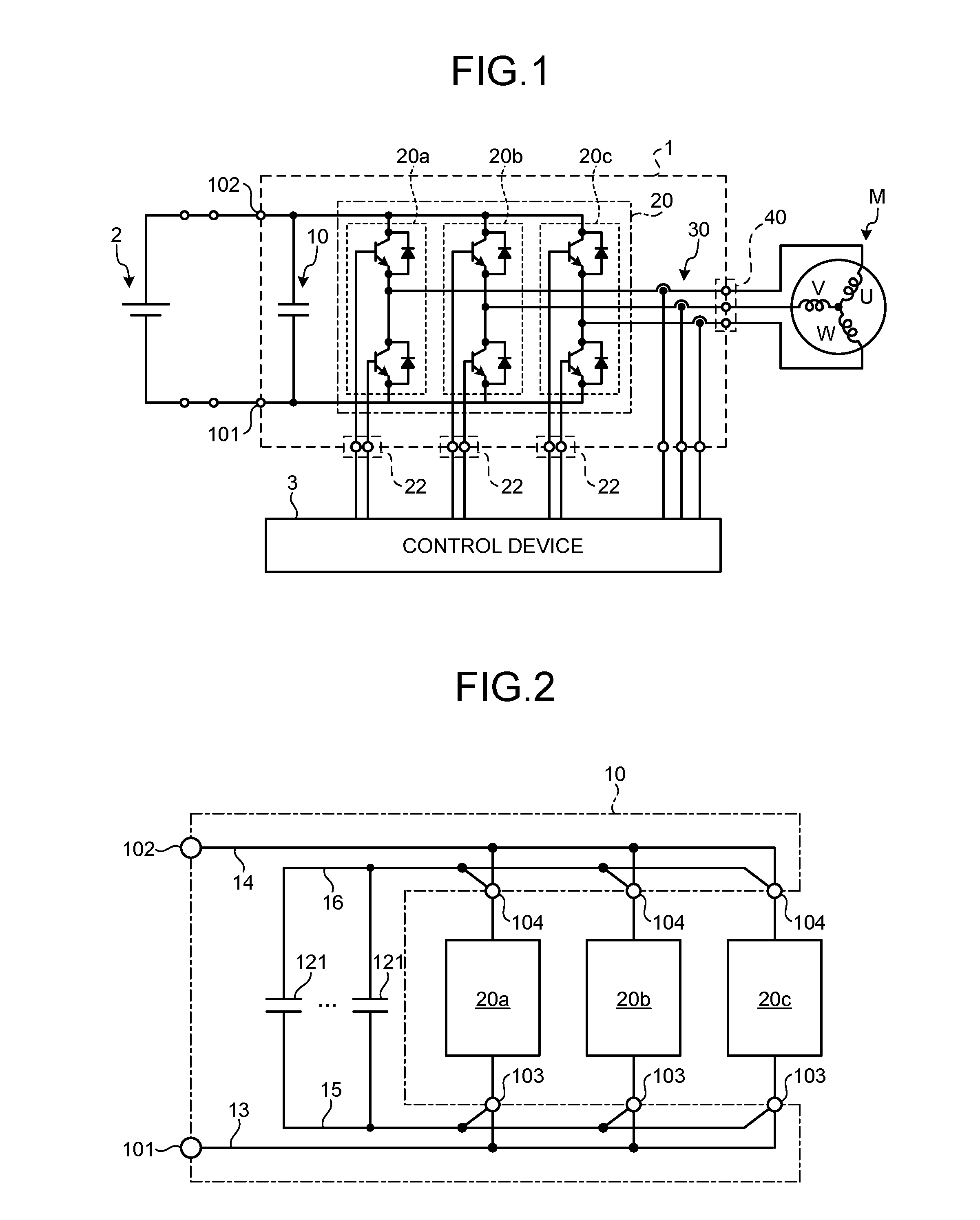
First, the circuit configuration of a power conversion apparatus according to a first embodiment will be described with reference to FIG. 1. FIG. 1 is a diagram illustrating the circuit configuration of the power conversion apparatus according to the first embodiment.
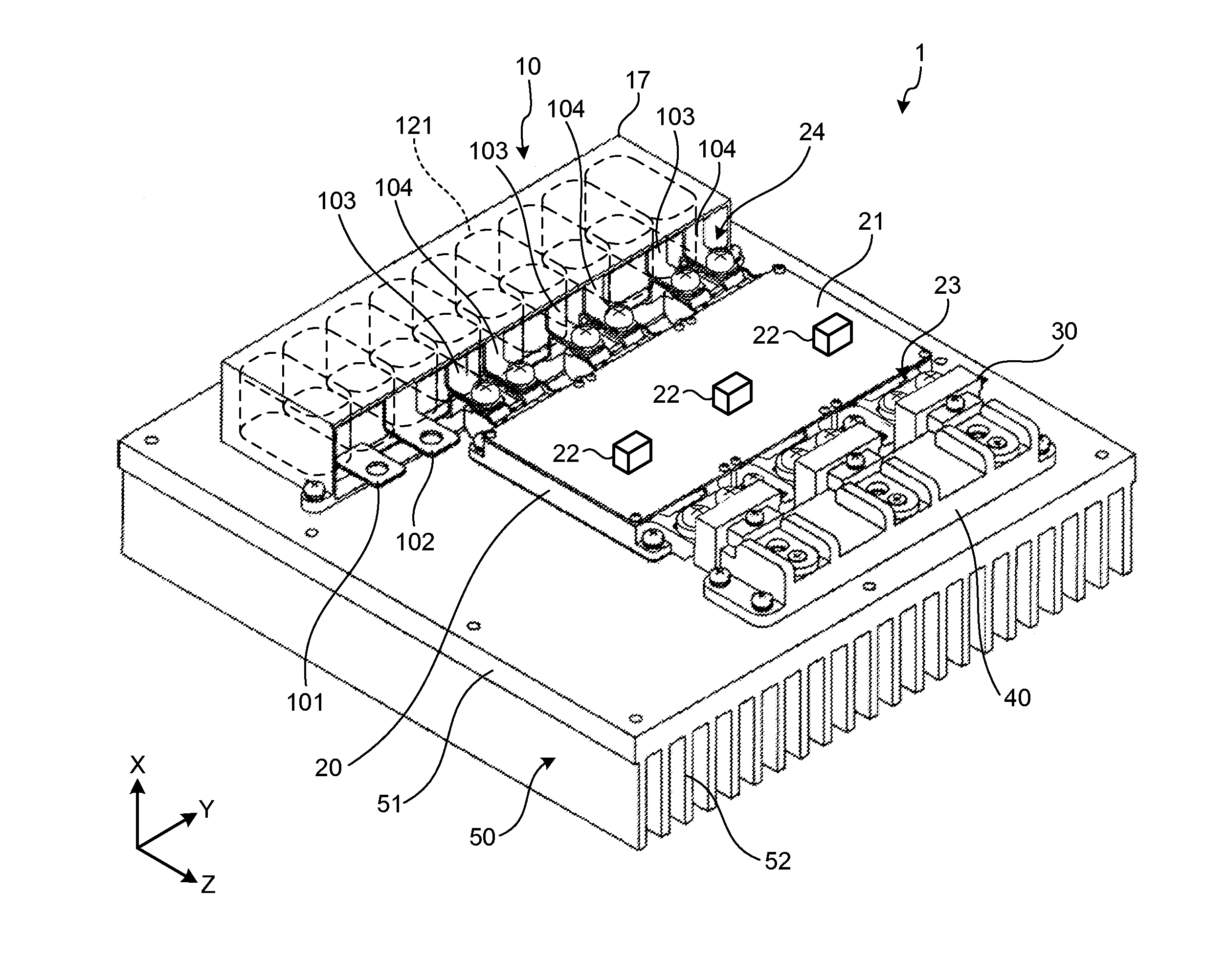
A power conversion apparatus 1 illustrated in FIG. 1 includes an inverter unit 20 that converts a DC voltage, which is input from a DC power source 2 to first connection portions 101 and 102 serving as input terminals, into a three-phase AC voltage and outputs the three-phase AC voltage to a three-phase motor M from output terminals provided to an output terminal block 40. In addition, the first connection portion 101 is connected to a negative side of the DC power source 2 and the first connection portion 102 is connected to a positive side of the DC power source 2.
The inverter unit 20 is a switching circuit provided with switching element sections 20a to 20c including a pair of serially connected semiconductor switche...
second embodiment
Next, a power conversion apparatus according to the second embodiment will be described. The power conversion apparatus according to the second embodiment is substantially identical to the power conversion apparatus 1 according to the first embodiment, except for the configuration of a main circuit capacitor. Hereinafter, the main circuit capacitor of the power conversion apparatus according to the second embodiment will be described in detail with reference to FIGS. 5A to 5C.
FIG. 5A is an exploded perspective view of a main circuit capacitor 10a according to the second embodiment, FIG. 5B is a see-through view explaining an inside of a case 17 of the main circuit capacitor 10a, and FIG. 5C is sectional view taken along line B-B of FIG. 5B.
As illustrated in FIG. 5A, the main circuit capacitor 10a according to the second embodiment is assembled by stacking a positive-side first wiring member 14a, a positive-side second wiring member 16a, a capacitor element unit 12a, a negative-side ...
third embodiment
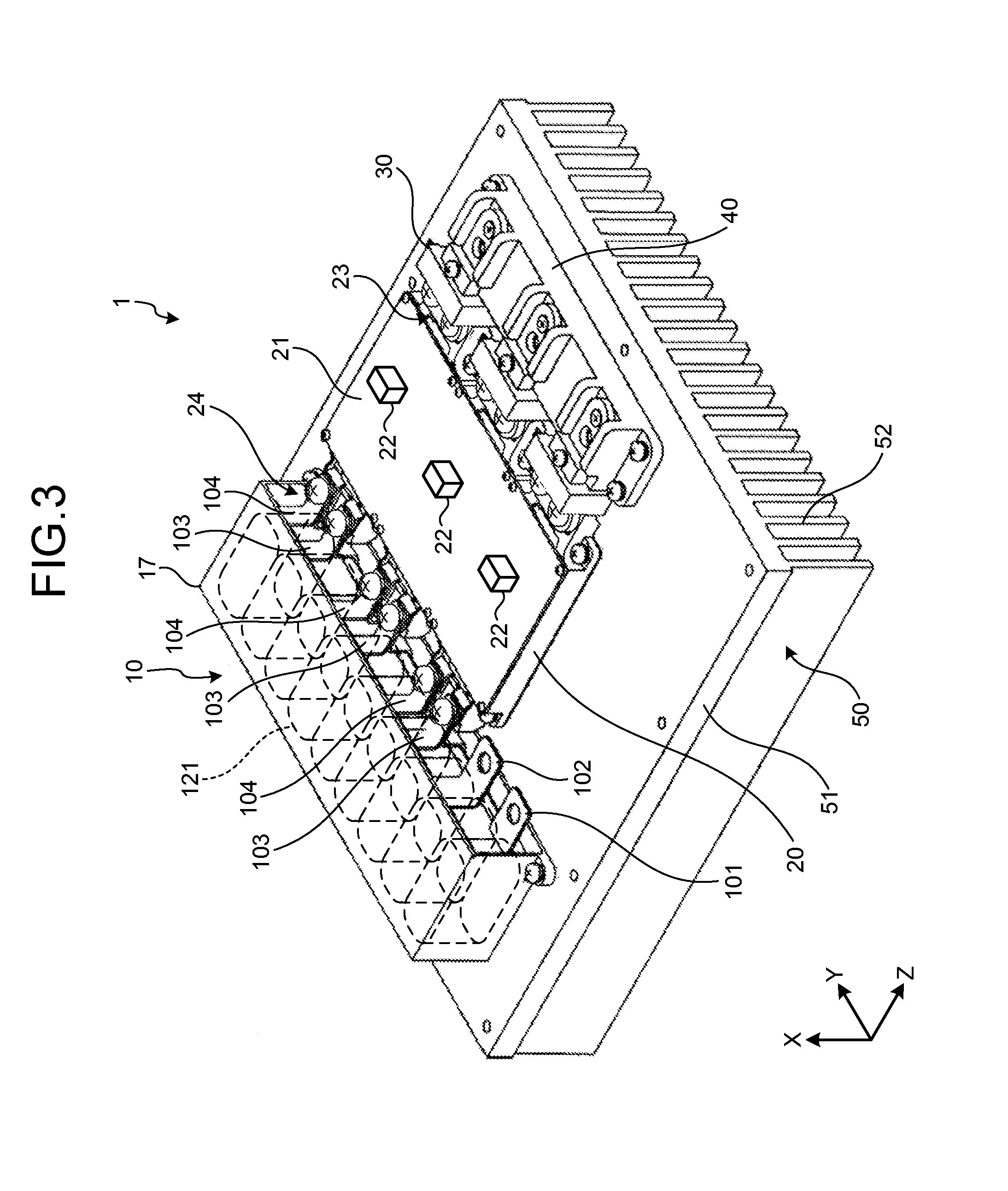
Next, a power conversion apparatus according to the third embodiment will be described. The power conversion apparatus according to the third embodiment has the same configuration as that of the power conversion apparatus 1 illustrated in FIG. 3, except for a difference in the configuration of connection places of a DC power source 2.
FIG. 6 is a perspective view illustrating the external appearance of a power conversion apparatus 1b according to the third embodiment. As illustrated in FIG. 6, in the power conversion apparatus 1b, an input terminal block 71 and a connection terminal block 73 are provided on the upper surface of a base 51. The input terminal block 71 is provided adjacent to an output terminal block 40 and the connection terminal block 73 is provided at a position facing first connection portions 101 and 102 protruding from a main circuit capacitor 10.
In the power conversion apparatus 1b, a pair of wiring members 72 and 72 with conductivity are installed between the in...
PUM
 Abstract
Description
Claims
Application Information