
Multifiber connectors for multicore optical fiber cables

Active Publication Date: 2011-09-22
OFS FITEL LLC
View PDF23 Cites 68 Cited by
  • Summary
  • Abstract
  • Description
  • Claims
  • Application Information

AI Technical Summary

Benefits of technology

[0014]A further aspect of the invention provides a multifiber ferrule, comprising a ferrule body having a plurality of guide holes therein for guiding a respective plurality of multicore fibers at an end of a multifiber optical fiber cable. The multicore fibers each have at least one flat side surface identifying a particular rotational orientation of the plurality of cores. The ferrule guide holes each have a shape including a flat side surface corresponding to the at least one flat side surface of the multicore fibers, such that alignment of the at least one flat side surface of each multicore fiber against the corresponding flat surface within its respective guide hole results in a rotational alignment of the plurality of cores.

Problems solved by technology

However, high-density configurations assembled using standard single-core fibers have proven to be extremely expensive to produce, since achieving physical contact between all of the fibers, when two connectors are mated, requires very precise control of the polishing process to ensure coplanarity (especially in the 72-fiber variant).
Also, the molded MT ferrules are very expensive to produce.
The production yields on 2D-array MT ferrules leads to significantly higher cost, as one hole out of position causes a ferrule to be rejected.
In addition, stacking fiber ribbons to produce the ribbon cordages, needed for the 2D configurations, leads to a relatively large, bulky, and expensive package.
Also, the flexibility of the ribbon cordage is adversely affected.

Method used


Image

  • Multifiber connectors for multicore optical fiber cables
  • Multifiber connectors for multicore optical fiber cables
  • Multifiber connectors for multicore optical fiber cables

Examples


Embodiment Construction

[0037]The present description of the invention is organized into the following sections:

[0038]1. Multicore Multifiber Connectors Using Circular Fibers

[0039]2. Multicore Multifiber Connectors Using D-Shaped Fibers

[0040]3. Alignment Techniques for D-Shaped Multicore Fibers[0041]3.1 Ramp Method[0042]3.2 Tapered Slot Method[0043]3.3 Slot Method[0044]3.4 Wedge Method

[0045]4. Multifiber Ferrules with D-Shaped Holes and D-Shaped Fibers

[0046]5. Multicore Multifiber Connectors Using Polygonal Fibers

[0047]6. Multicore Multifiber Connectors Using Other Fiber Shapes

[0048]7. General Techniques

[0049]8. Conclusion

[0050]1. Multicore Multifiber Connectors Using Circular Fibers

[0051]To address the shortcomings of the current approach, multicore fibers (MCF), which can be butt-coupled with specially designed 2-dimensional VCSEL and PiN photo detector arrays to facilitate simultaneous transmission over several cores, within each fiber, are utilized.

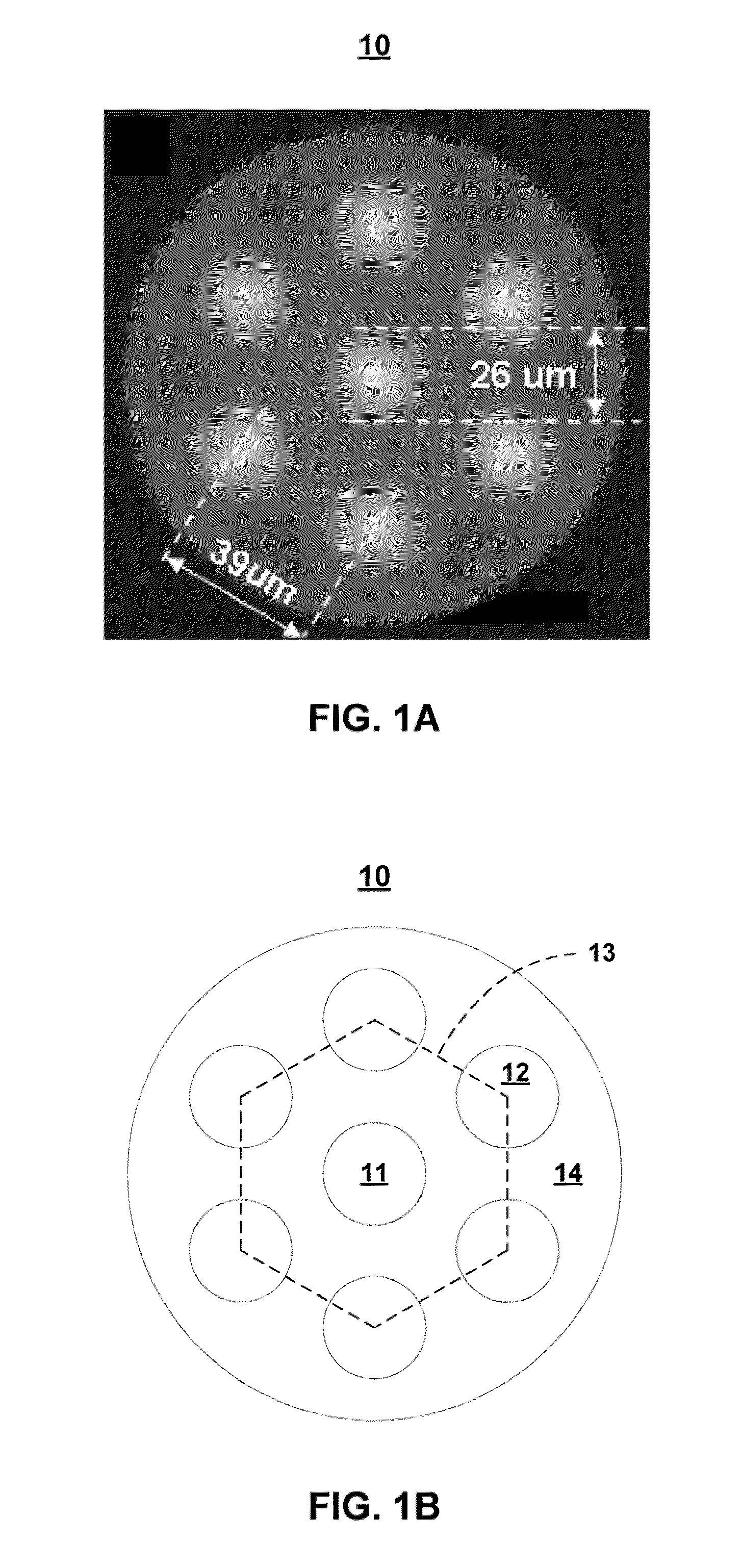
[0052]FIGS. 1A and 1B show, respectively, a cross sect...


PUM

PropertyMeasurementUnit
Distanceaaaaaaaaaa
Distanceaaaaaaaaaa
Shapeaaaaaaaaaa

Abstract

Structures and techniques are described relating to the alignment of multicore fibers within a multifiber connector. These structures and techniques include: multicore fibers having a number of different shapes, including, for example, circular, elliptical, D-shaped, double D-shaped, and polygonal; multifiber ferrules, having a plurality of fiber guide holes therein of various shapes; alignment fixtures for aligning multicore fibers within multifiber ferrules; and various multicore fiber alignment techniques.

Description

CROSS REFERENCE TO RELATED APPLICATIONS[0001]The present application claims the priority benefit of the following United States provisional patent applications, which are owned by the assignee of the present application, and which are incorporated herein by reference in their entirety:[0002]U.S. Prov. Pat. App. Ser. No. 61 / 314,165, filed on Mar. 16, 2010.BACKGROUND OF THE INVENTION[0003]1. Field of the Invention[0004]The present invention relates generally to the field of fiber optics, and in particular to improved multifiber connectors for multicore optical fiber cables.[0005]2. Background Art[0006]The ever increasing demand for high-density, high-speed parallel optical data links, for super-computer and data-center applications, has spawned significant interest in passive optical devices designed to facilitate reliable, cost-effective deployment. In multi-channel parallel links for super computers and data centers, thousands of optical links, operating at 1 Gb / s to 10 Gb / s, may be...

Claims


Application Information

Patent Timeline
IPC IPC(8): G02B6/36G02B6/00G02B6/10B23Q3/00
CPCG02B6/3851G02B6/3885G02B6/3893Y10T29/49895G02B6/02042Y10T29/49174G02B6/4403G02B6/3871Y10T156/1052G02B6/245G02B6/3834G02B6/3843G02B6/3861G02B6/3863
Inventor BRADLEY, KELVIN B.KIM, JINKEESANDELS, GREGORY A.
Owner OFS FITEL LLC
Learn More