

Motorcycle cowl structure
a technology for motorcycles and cowls, applied in the direction of roofs, cycle equipment, transportation and packaging, etc., can solve the problems that the conventional cowl structure does not take into account, and achieve the effect of suppressing the flow of air
- Summary
- Abstract
- Description
- Claims
- Application Information
AI Technical Summary
Benefits of technology
Problems solved by technology
Method used
Image


Examples
first embodiment
[0050]the present invention is first described with reference to the drawings.
[0051]Referring to FIG. 1, a motorcycle 10 is a straddle-ride type vehicle on which a rider and a pillion passenger straddling a vehicle body.
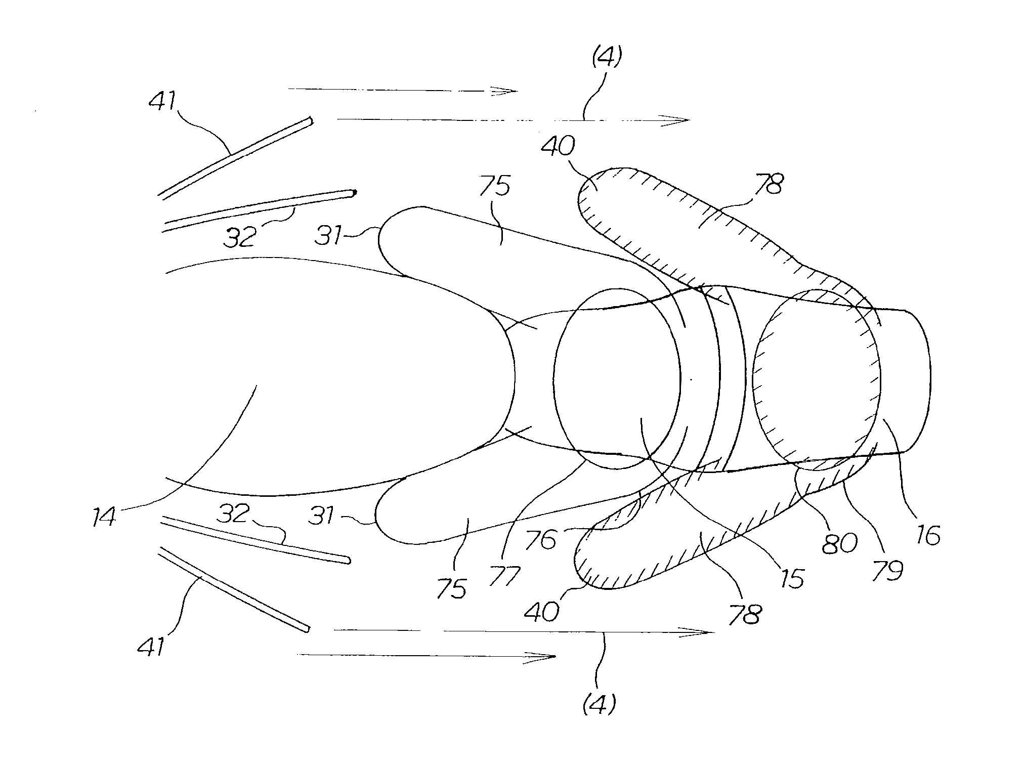
[0052]The motorcycle 10 includes a front fork 11 at a front portion of the vehicle, a front wheel 12 rotatable at the lower portion of the front fork 11, and a rear wheel 13 at a rear lower portion of the vehicle. Further, the motorcycle 10 includes a fuel tank 14, a rider seat 15 on which the rider sits and the pillion passenger seat 16 on which a pillion passenger sits in this order from the upper center to rear of the vehicle.
[0053]A front fender 18 covering the front wheel 12 from above is mounted to the front fork 11 so as to prevent mud water from being splashed upward. A radiator 19 is disposed rearward of the front wheel 12.
[0054]An exhaust pipe 20 extending rearward is installed on the left lateral surface of the lower portion of the vehicle body. A muffler ...
second embodiment
[0079]the present invention is next described with reference to the drawings.
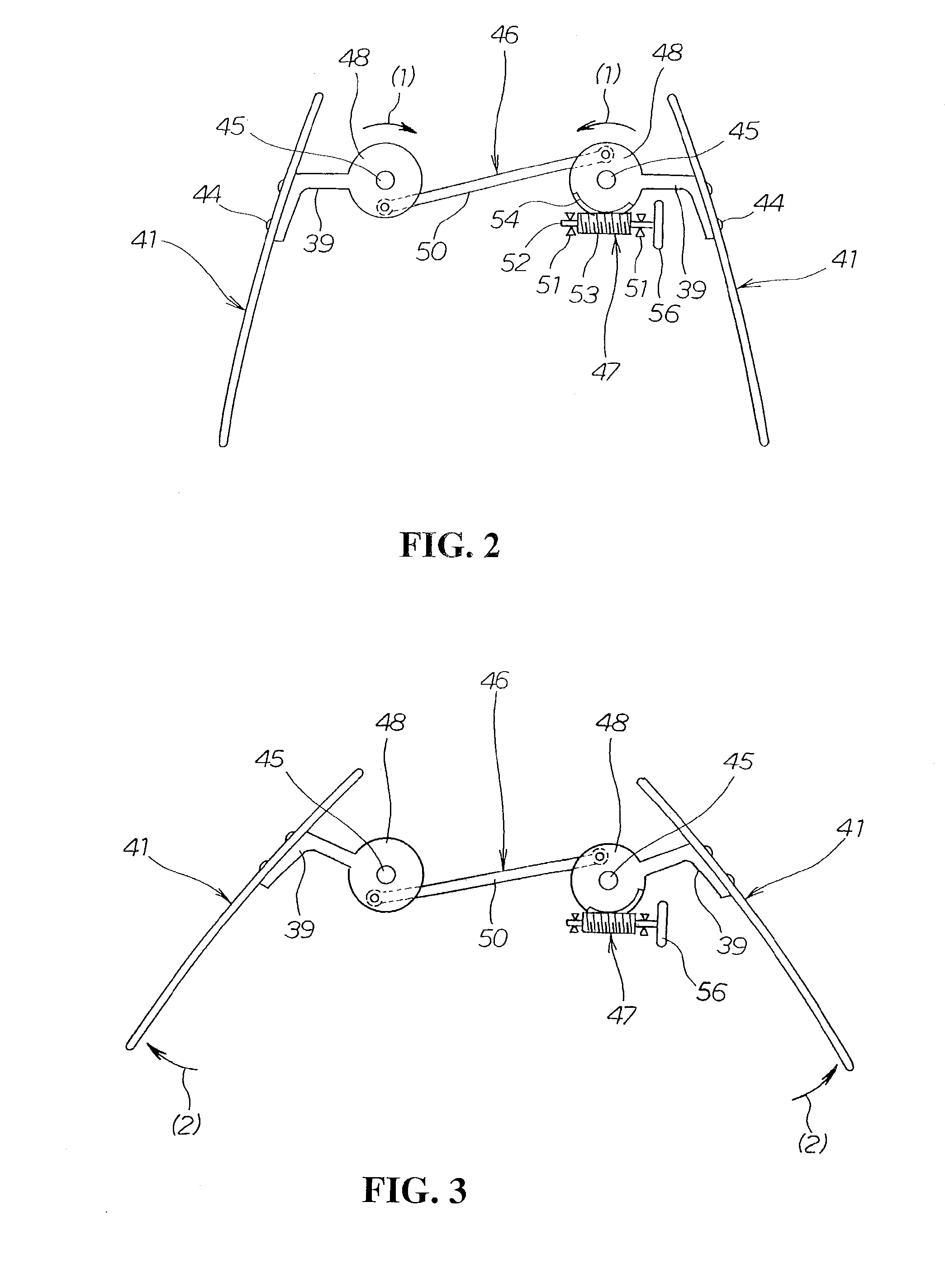
[0080]FIG. 6 illustrates the second embodiment. In the basic configuration of the first embodiment in FIG. 2, the left and right arms 39 are mechanically interlinked with each other by means of a winding transmission mechanism 57. The other elements are the same as in FIG. 2. Therefore, a detailed description of reference numerals in FIG. 6 that are common with FIG. 2 is omitted.
[0081]The winding transmission mechanism 57 includes pulleys 58 provided on the left and right support shafts 45; and a cross-wound wire 59 wound around the left and right pulleys 59. In addition, it may be reasonable that a belt is used in place of the wire.
[0082]When the handle 56 is turned to turn the right pulley 58 in the direction of arrow (1), the turning force of the right pulley 58 is transmitted to the left pulley 58 via the cross-wound wire 59. In this way, the left movable cowl portion 41 is opened in conjunction with th...
third embodiment
[0084]the present invention is next described with reference to the drawings.
[0085]FIG. 7 illustrates the third embodiment. In the basic configuration of the first embodiment in FIG. 2, an electric motor 60 is installed on each of left and right movable cowl portions 41 without the use of the link mechanism. The other elements are the same as in FIG. 2. Therefore, a detailed description of reference numerals in FIG. 7 that are common with FIG. 2 is omitted.
[0086]The electric motor 60 is connected to the proximal portion of the arm 39. The movable cowl portion 41 is opened and closed through the turning of the arm 39 by the electric motor 60.
[0087]The left and right movable cowl portions 41 are provided with the respective left and right electric motors 60; therefore, the structure is simpler than the structure provided with the interlink mechanism. Additionally, the structure having a left-right weight balance is provided.
[0088]In addition, in view of the left-right weight balance o...
PUM
 Abstract
Description
Claims
Application Information