Surgical instrument

a surgical instrument and a technology for manipulating instruments, applied in the field of medical instruments, can solve the problems of difficult operation and use of endoscopic and laparoscopic instruments, difficult to master common tasks such as suturing, knotting and fine dissection, and still not providing enough dexterity to allow the surgeon

Inactive Publication Date: 2011-09-29
CAMBRIDGE ENDOSCOPIC DEVICES
View PDF64 Cites 17 Cited by
  • Summary
  • Abstract
  • Description
  • Claims
  • Application Information

AI Technical Summary

Benefits of technology

To accomplish the foregoing and other advantages and features of the present invention there is provided a surgical instrument comprising: an instrument shaft having proximal and distal ends; a tool disposed from the distal end of the instrument shaft; a control handle coupled from the proximal end of the instrument shaft; a distal bendable member for coupling the distal end of the instrument shaft to the tool; a proximal bendable member for coupling the proximal end of the instrument shaft to the control handle; actuation means extending between distal and proximal bendable members for coupling motion of the proximal bendable member to the distal bendable member for controlling the positioning of the tool and a locking mechanism for fixing the position of the tool at a selected position. The locking mechanism includes a ball and socket arrangement disposed about said proximal bendable member and a locking member for locking the ball and socket arrangement and having locked and unlocked states. The ball and socket arrangement includes a compression ring supported from the control handle, having an outer surface for support of the locking member thereabout and having an inner surface defining an at least partially spherical shaped socket. The ball and socket arrangement further includes a hollow ball member having an internal hollow chamber and an outer at least partially spherical shaped surface which mates with the at least partially spherical shaped socket.
In accordance with other aspects of the present invention the hollow ball member may be supported within the socket and constructed and arranged with at least a portion of the proximal bendable member disposed in the internal hollow chamber of the hollow ball member; the compression ring may include an annular resilient base member, and a plurality of stiffener segments that are disposed about the annular resilient base member; the annular resilient base member may include a plurality of spacedly disposed hinges that define therebetween a plurality of support segments; the plurality of stiffener segments may be disposed over the respective plurality of support segments; each stiffener segment preferably has, on a top surface thereof, a series of ribs, wherein the ribs are spaced apart and extend circumferentially; including at least a hub for supporting the compression ring; including a plurality of struts for supporting the hub from the control handle; wherein each hinge includes a passage for receiving a respective strut; including a rotation means disposed adjacent the control handle and rotatable relative to the control handle for causing a correspond may comprise a rotation knob that is adapted to rotate the tool about a distal tool roll axis and said rotation knob is disposed between said control handle and proximal bendable member; wherein the control handle may comprise a pistol grip handle having an engagement horn to assist in holding the handle; including an actuation lever supported from the pistol grip handle and a multiple linkage mechanism for supporting the actuation lever; and including a tool actuation cable that extends from the tool to the handle, a slider for capturing the proximal end of the tool actuation cable and an actuation lever supported at the handle for controlling the translation of the slider.
In accordance with other aspects and features of the present invention there is provided a medical instrument comprising a proximal control handle and a distal tool that are intercoupled by an elongated instrument shaft that is meant to pass internally of an anatomic body, proximal and distal bendable members that respectively intercouple the proximal control handle and the distal tool with the instrument shaft, cable actuation means disposed between said bendable members, for controlling the po

Problems solved by technology

Endoscopic and laparoscopic instruments currently available in the market are extremely difficult to learn to operate and use, mainly due to a lack of dexterity in their use.
As a result, common tasks such as suturing, knotting and fine dissection have become challenging to master.
However, even so these instruments still do not provide enough dexterity to allow the surgeon to perform common tasks such as suturing, particularly at any arbitrarily selected orientation.
During the 1990s, the growth rate of MIS was tremendous; however, in the last few years t

Method used


Image

  • Surgical instrument
  • Surgical instrument
  • Surgical instrument

Examples


first embodiment

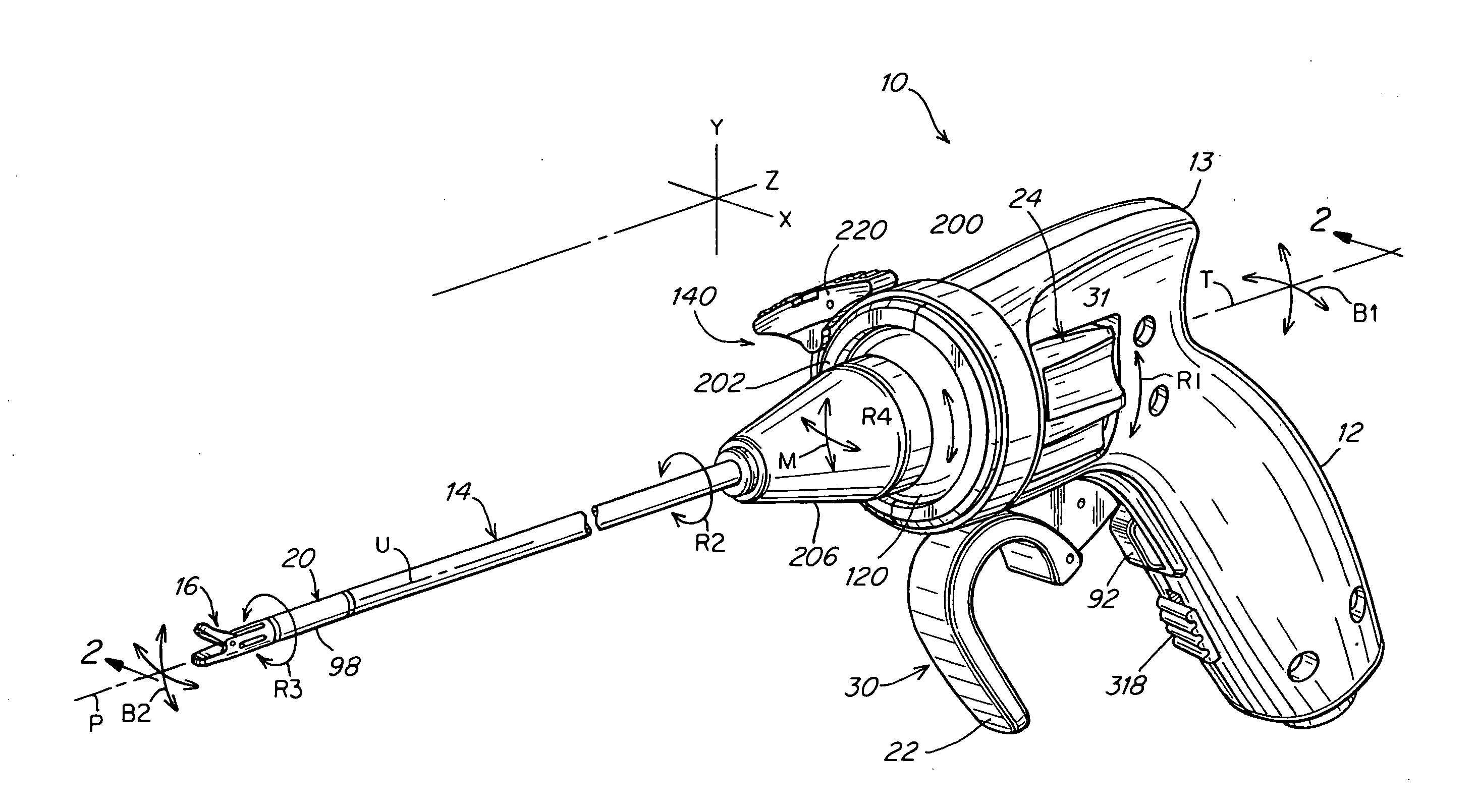
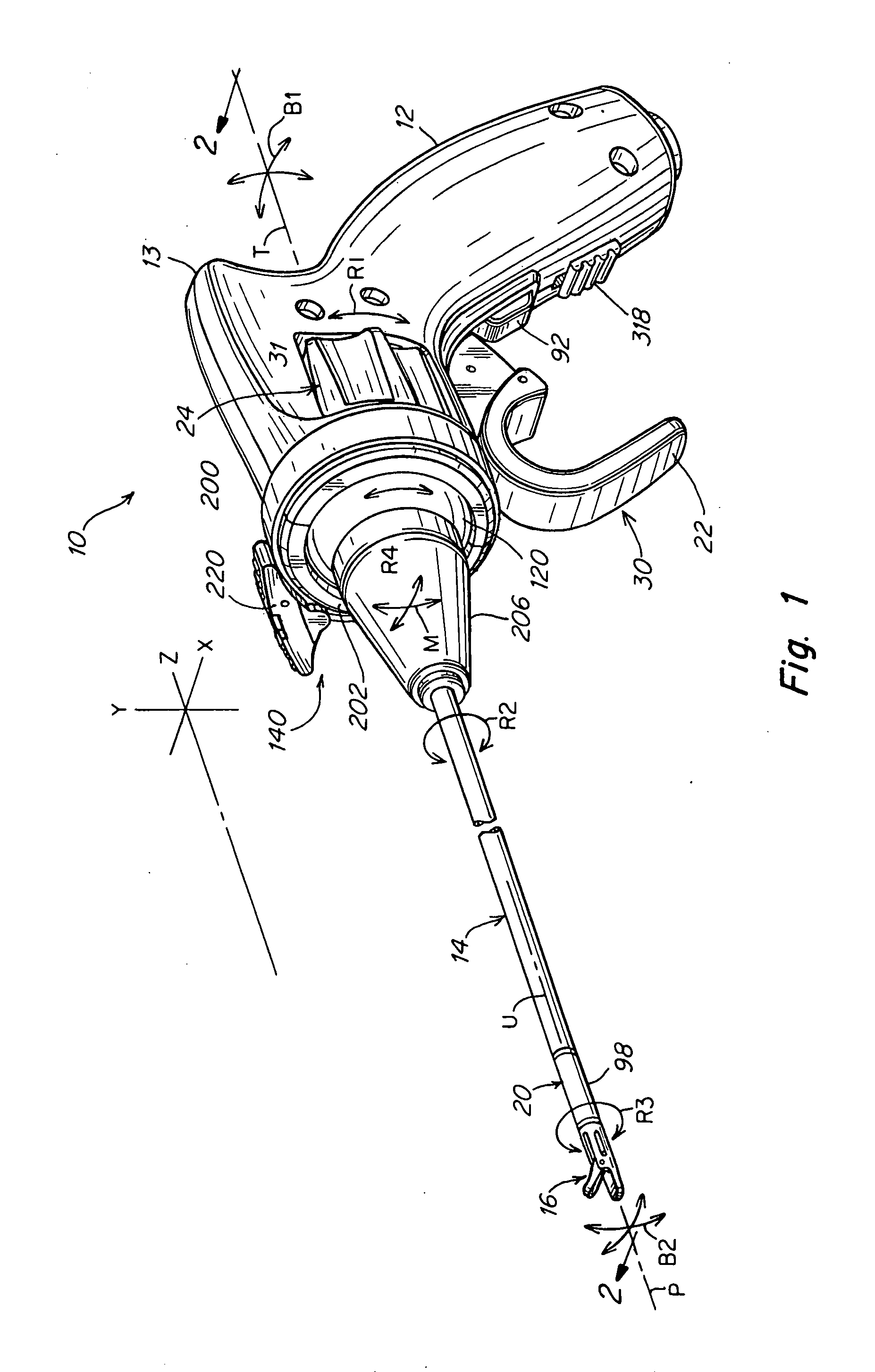
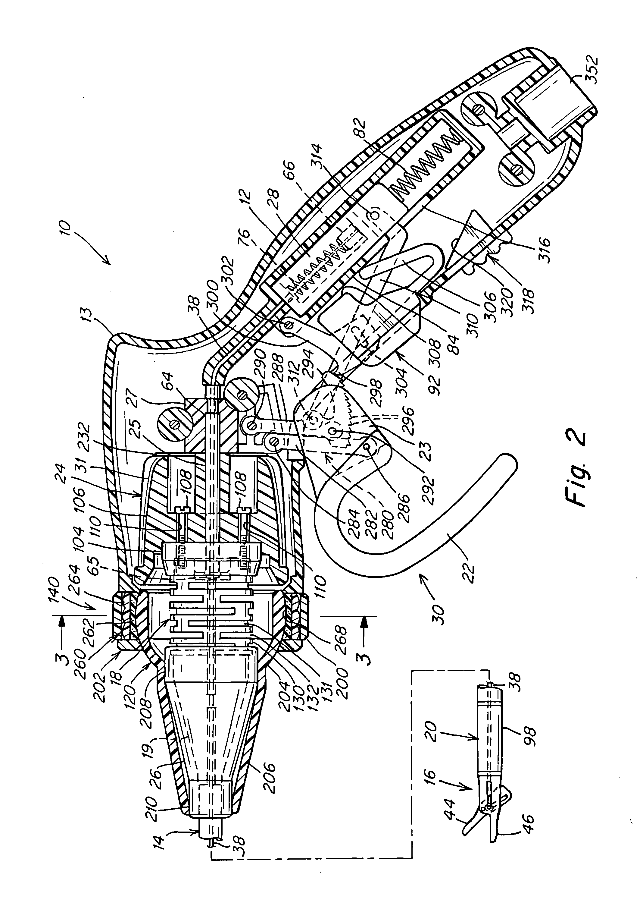
There are two fewer discs 130 in the proximal bending member than in the past instrument. The conical portion 19 is seated in adapter 26 to which the proximal end of shaft portion 14 is mounted. The shaft portion 14 has an outer shaft tube 32, inner shaft tube 34 and shaft filler 36 with lumens or passages for cables 38 and 100 as can be seen in FIG. 5. The distal end of the shaft portion 14 supports the distal bending member 20 to which the end effector 16 is attached. The end effector in this first embodiment is depicted as a grasper but other configurations of end effector may also be used. The adapter 26 is free to rotate within the neck 206 of ball 120 at bearing surfaces 208, 210.

The improved angle locking means 140 is now described. As can be best seen in FIG. 6, instead of the cinch ring clamping split hub segments to the ball 120 as in, for example, the instrument shown in Ser. No. 11 / 649,352, the hub 202 is connected to the handle 12 by struts 230 with spherically shaped i...

third embodiment

In this third embodiment the rear links 288 have been modified by deleting the ratchet arms 294 and the link 300 and release button 92 have been removed as well. Still another version of the instrument might include a dissector tool (not shown) as an end effector. Either the scissors or dissector may be additionally used as a cautery tool by the addition of a banana plug connector 354 installed in the socket 352 at the base of the handle. Refer to FIG. 10 that illustrates the location of the banana plug connector 354 and associated socket 352. The connector may be plugged into a jack connected to an electrical generation source that can heat the end effector by induction to a temperature suitable for cauterization of tissue. The banana plug connector 354 is electrically connected to the end effector by means of cable 38 and connecting wire 356 which is wrapped around cable 38 at 358 and is protected by insulating sheath 360 as best seen in FIG. 10. The sheath 360 may extend from the...


PUM


Abstract

A surgical instrument that includes an instrument shaft having proximal and distal ends; a tool disposed from the distal end of the instrument shaft; a control handle coupled from the proximal end of the instrument shaft; a distal bendable member for coupling the distal end of the instrument shaft to the tool; a proximal bendable member for coupling the proximal end of the instrument shaft to the control handle; actuation means extending between the distal and proximal bendable members for coupling motion of the proximal bendable member to the distal bendable member for controlling the positioning of the tool and a locking mechanism for fixing the position of the tool at a selected position. The locking mechanism includes a ball and socket arrangement disposed about the proximal bendable member and a locking member for locking the ball and socket arrangement and having locked and unlocked states. The ball and socket arrangement includes a compression ring supported from the control handle, having an outer surface for support of the locking member thereabout and having an inner surface defining an at least partially spherical shaped socket. The ball and socket arrangement further includes a hollow ball member having an internal hollow chamber and an outer at least partially spherical shaped surface which mates with the at least partially spherical shaped socket.

Description

TECHNICAL FIELDThe present invention relates in general to medical instruments, and more particularly to manually-operated surgical instruments that are intended for use in minimally invasive surgery or other forms of surgical or medical procedures or techniques. The instrument described herein is primarily for a laparoscopic procedure, however, it is to be understood that the instrument of the present invention can be used for a wide variety of other procedures, including intraluminal procedures.BACKGROUND OF THE INVENTIONEndoscopic and laparoscopic instruments currently available in the market are extremely difficult to learn to operate and use, mainly due to a lack of dexterity in their use. For instance, when using a typical laparoscopic instrument during surgery, the orientation of the tool of the instrument is solely dictated by the location of the target and the incision. These instruments generally function with a fulcrum effect using the patient own incision area as the ful...

Claims


Application Information

Patent Timeline
IPC IPC(8): A61B17/00
CPCA61B17/00234A61B2017/2946A61B2017/293
Inventor PEINE, WILLIAM J.CHAMORRO, ANDRESLEE, WOOJIN
Owner CAMBRIDGE ENDOSCOPIC DEVICES
Why Eureka
Try Eureka