Universal portable workstation

a workstation and universal technology, applied in the field of universal portable workstations, can solve the problems of insufficient workspace or countertop space, inconvenient transportation, and heavy weight of folding card tables, and achieve the effects of convenient transportation, convenient transportation, and convenient us

Inactive Publication Date: 2011-10-13
COFFMAN AVON C +1
View PDF20 Cites 51 Cited by
  • Summary
  • Abstract
  • Description
  • Claims
  • Application Information

AI Technical Summary

Benefits of technology

[0008]The portable workstation of the present invention may also include one or more attachment clamps that couples one end of the workstation to an existing work surface. Existing work surfaces that may support the portable workstation of the present invention are countertops, tables, bars, desks, tailgates, railings, ledges, or any other work surfaces. The attachment clamp(s) may be hooks, straps, elastic cords, clamps, hook and loop fastener (VELCRO®), or any combination thereof or any other attachment methods now known or hereafter developed. The attachment clamp(s) of the present invention allows a user to develop some continuity between the existing work surface and the temporary, portable workstation of the present invention.

Problems solved by technology

Further, many people participate in recreational activities in places with confined spaces and limited workspace such as recreational vehicles, boats, campsites, tail gate parties, barbecues, or the like.
Often these locations have an inadequate area of workspace or countertop space, if any.
Folding card tables are portable, but often bulky as they include a solid one-piece table surface.
This is often difficult to find in any mode of transportation.
Further, existing portable tables do not attach to the existing surface, so there is always some discontinuity or a joint where items may fall through.

Method used


Image

  • Universal portable workstation
  • Universal portable workstation
  • Universal portable workstation

Examples


Embodiment Construction

[0024]The following detailed description of the invention references the accompanying drawing figures that illustrate specific embodiments in which the invention can be practiced. The embodiments are intended to describe aspects of the invention in sufficient detail to enable those skilled in the art to practice the invention. Other embodiments can be utilized and changes can be made without departing from the scope of the present invention. The present invention is defined by the appended claims and the description is, therefore, not to be taken in a limiting sense and shall not limit the scope of equivalents to which such claims are entitled.

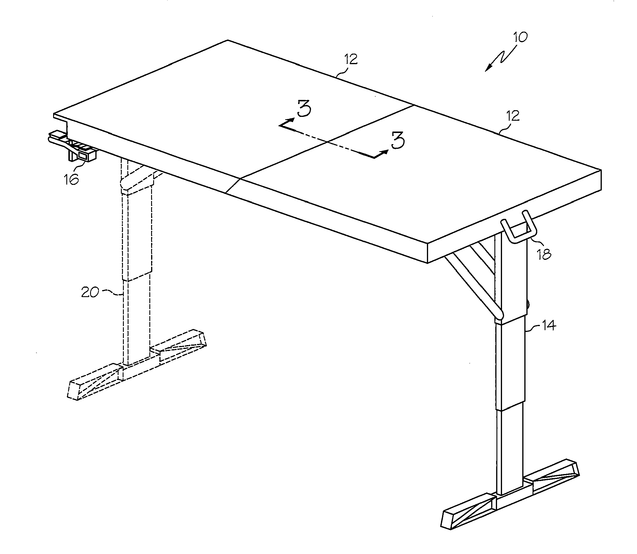
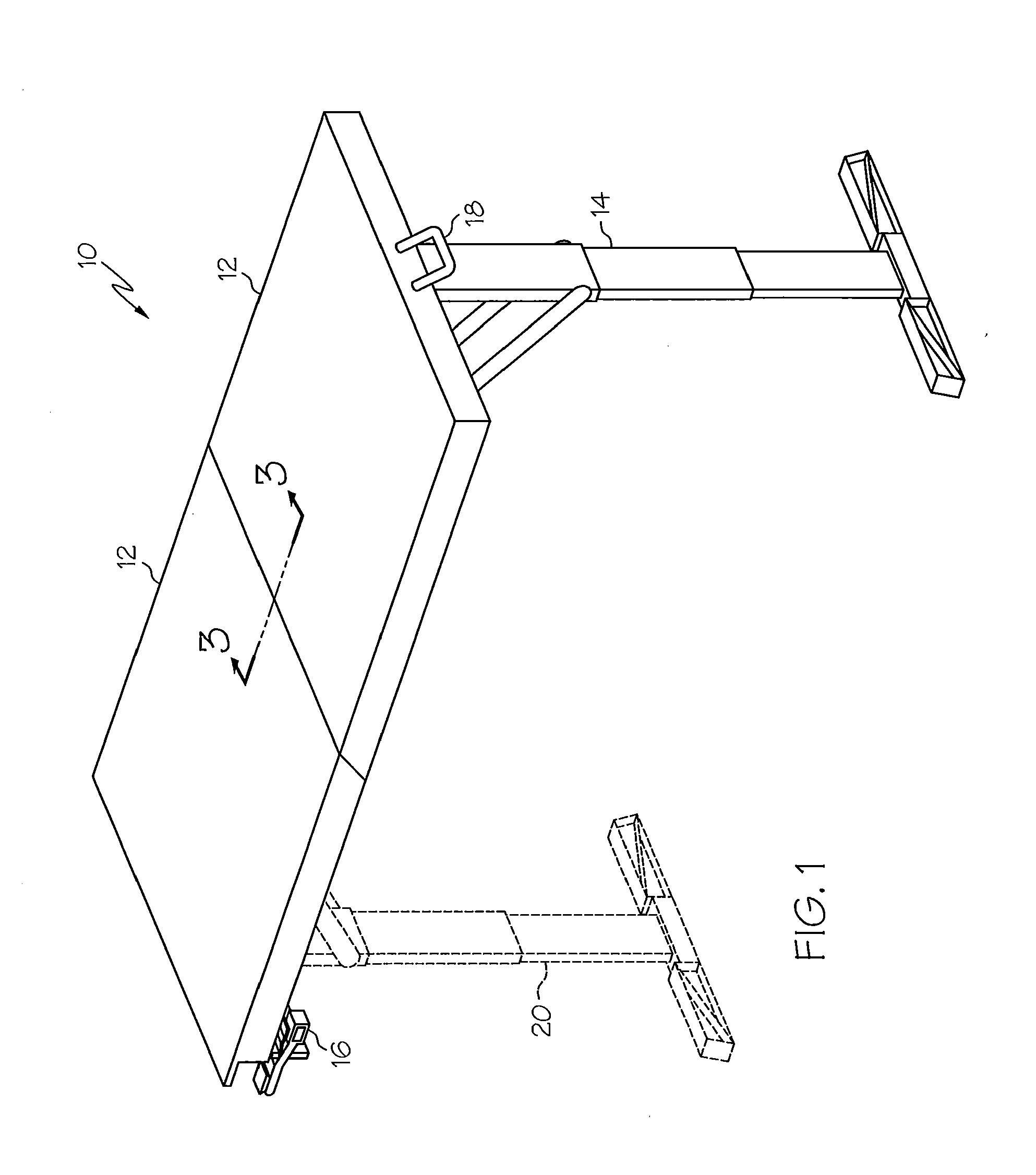
[0025]FIG. 1 illustrates an embodiment of portable workstation 10 of the present invention. Portable workstation 10 comprises a work surface 12, at least one adjustable support leg 14, and an attachment clamp 16. Portable workstation 10 may also include a handle 18 and a second adjustable support leg 20. Handle 18 may be slideably coupled to w...


PUM


Abstract

The present invention is directed to a universal portable workstation that can be temporarily coupled to an existing fixture, the portable workstation comprising an adjustable support leg assembly, a first table section, a second table section and an attachment clamp. The support leg assembly includes one fixed leg and at least one adjustable leg configured for relative telescopic movement. The support leg assembly is pivotally coupled to a first table section that is configured to house the support leg assembly in a retracted position. The height of the workstation is adjustable and can be fixed by a height adjustment lock. First table section and second table section are hingedly coupled so that the two sections can be in an extended, flat position and a folded, retracted position. The attachment clamp is configured to temporarily fixedly couple an end of the second table section to the existing fixture.

Description

CROSS-REFERENCE TO RELATED APPLICATIONS[0001]This application claims the benefit of U.S. Provisional Patent Application No. 61 / 322,182 having a filing date of Apr. 8, 2010 and U.S. Provisional Patent Application No. 61 / 322,434 having a filing date of Apr. 9, 2010 both of which are incorporated herein by reference to the extent permitted by law.BACKGROUND OF THE INVENTION[0002]Many people in the world live in apartments, houses, or dorm rooms that have small kitchens with limited (or no) countertops or work surfaces. Further, many people participate in recreational activities in places with confined spaces and limited workspace such as recreational vehicles, boats, campsites, tail gate parties, barbecues, or the like. Often these locations have an inadequate area of workspace or countertop space, if any. Since people also like to combine meals and food while living or participating in a recreational activity, at times of food preparation or presentation, there is a need to temporaril...

Claims


Application Information

Patent Timeline
Patent Type & Authority Applications(United States)
IPC IPC(8): A47B3/02A47B9/20
CPCA47B3/0911A47B9/08A47B2200/0085B25H1/02B25H1/16A47B9/14
Inventor COFFMAN, ZACHARY M.
Owner COFFMAN AVON C
Why Eureka
Try Eureka