Method And System For Decomposing Complex Shapes Into Curvy RHTS For Rasterization

a complex shape and rasterization technology, applied in the field of communication systems, can solve the problems of limiting the size of both the image sensor and the lens, the inability to integrate large image sensors with advanced processing, and the limited resolution of the camera phon

Active Publication Date: 2011-10-27
AVAGO TECH INT SALES PTE LTD
View PDF1 Cites 17 Cited by
  • Summary
  • Abstract
  • Description
  • Claims
  • Application Information

AI Technical Summary

Benefits of technology

The technical effect of this patent is that it describes how to break down complicated shapes into smooth lines for better visual representation during image processing. This can improve the quality and speed of creating images from scanners or other devices.

Problems solved by technology

The technical problem addressed by this patent is how to improve the quality and functionality of camera phones while maintaining their compact design and efficient transmission capacity.

Method used


Image

  • Method And System For Decomposing Complex Shapes Into Curvy RHTS For Rasterization
  • Method And System For Decomposing Complex Shapes Into Curvy RHTS For Rasterization
  • Method And System For Decomposing Complex Shapes Into Curvy RHTS For Rasterization

Examples


Embodiment Construction

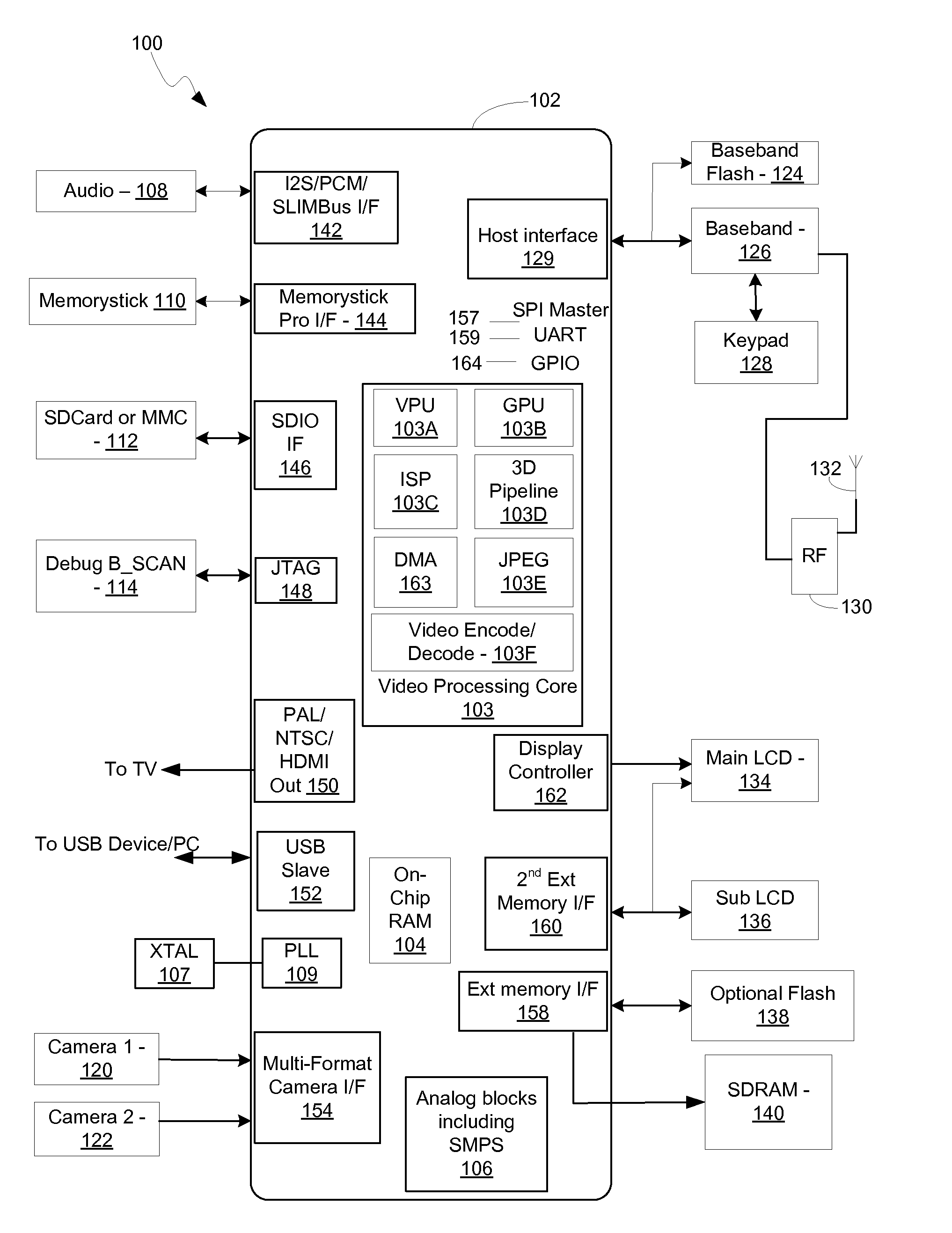
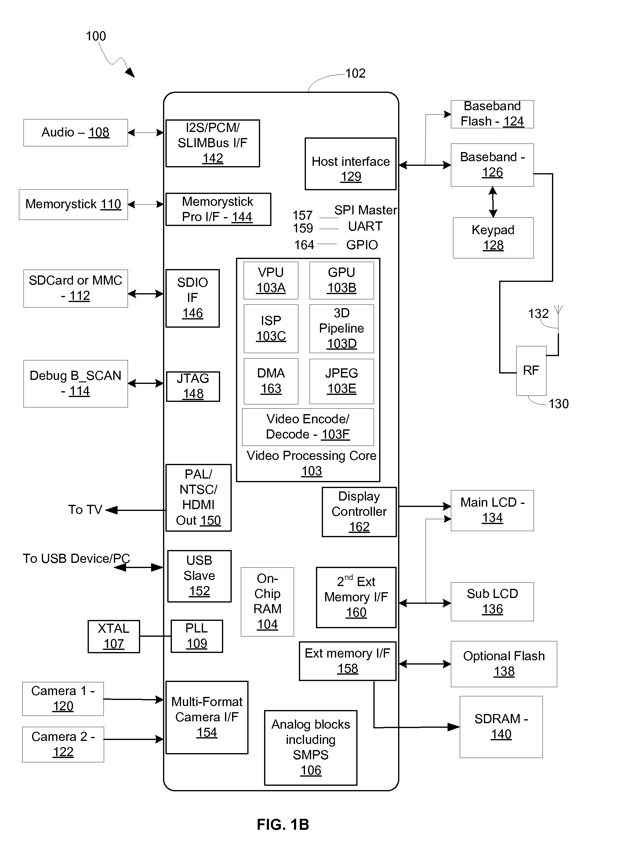
[0032]Certain embodiments of the invention can be found in a method and system for decomposing complex shapes into curvy RHTs for rasterization. A curved primitive that comprises a closed 2D complex shape, may be decomposed into a plurality of curvy right horizontal trapezium (RHT) primitives. A curvy RHT primitive may be referred to as a curvy RHT. Pixel rows that may be covered by each of the plurality of curvy RHT primitives may be determined. For each curvy RHT primitive, pixel counters for each pixel covered by each of the plurality of curvy RHT primitives may be incremented or decremented. Pixels which are covered by the curved primitive may be determined based on the pixel counters. Tile based color rendering of the curved primitive may be performed for the pixels that are determined to be covered by the curved primitive.

[0033]The curved primitive may comprise a curved exterior boundary that may be decomposed into a plurality of joined Bezier curves and / or curve segments. The...


PUM


Abstract

A complex curved primitive is decomposed into curvy RHTs comprising a curved portion and horizontal and vertical lines. Pixel rows covered by curvy RHTs are determined. RHT pixels covered by the curved primitive are determined with counters. Tile based color rendering is performed for covered pixels. The primitive path is decomposed into Bezier curves. Curvy RHTs may overlap and may cover pixels that are not covered by the curved primitive. Pixel rows are located by traversing an RHT path and the direction of traversing may determine pixel counts. Pixel coverage and tile coverage information is stored in memory. Pixels may be rendered in parallel. The curved primitive is rendered in a tile binning phase and a tile rendering phase. Tile rendering comprises a pixel coverage first pass which determines pixels covered by said curved primitive and a color rendering second pass.

Description


Claims


Application Information

Patent Timeline
Owner AVAGO TECH INT SALES PTE LTD
Why Eureka
Try Eureka