Image Forming Apparatus

Active Publication Date: 2011-10-27
BROTHER KOGYO KK
View PDF3 Cites 9 Cited by
  • Summary
  • Abstract
  • Description
  • Claims
  • Application Information

AI Technical Summary

Benefits of technology

[0009]According to an aspect of the present invention, an image forming apparatus is provided. The image forming apparatus includes an image forming unit, which is configured to form an image on a recording sheet, a return-sheet conveyer unit, which is configured to convey the recording sheet carried from the image forming unit along a return-sheet path to return to the image forming unit, an upper frame unit, which includes a pair of side frames and is configured to support the image forming unit in a position between the pair of side frames, and a pair of lower frames, which are arranged to have a predetermined amount of clearance there-between and to have the return-sheet conveyer unit in the clearance, and are configured to be less rigid than the upper frame unit and to support lower sections of the pair of side frames. A vertical position of the return-sheet conveyer unit with respect to the image forming unit is defined with reference to the upper frame unit by having at least a part of the return-sheet conveyer unit aligned to be in contact with the upper frame unit.

Problems solved by technology

In the above-mentioned printers, however, when the return-sheet conveyer unit is arranged in the lower frame, the return-sheet conveyer unit may be misaligned, specifically in a vertical direction, with respect to the image forming unit arranged in the upper frame due to the deformation of the lower frame.
When the returning-sheet path is rough, the sheet may not be supplied to the image forming unit correctly.

Method used


Image

  • Image Forming Apparatus
  • Image Forming Apparatus
  • Image Forming Apparatus

Examples


Embodiment Construction

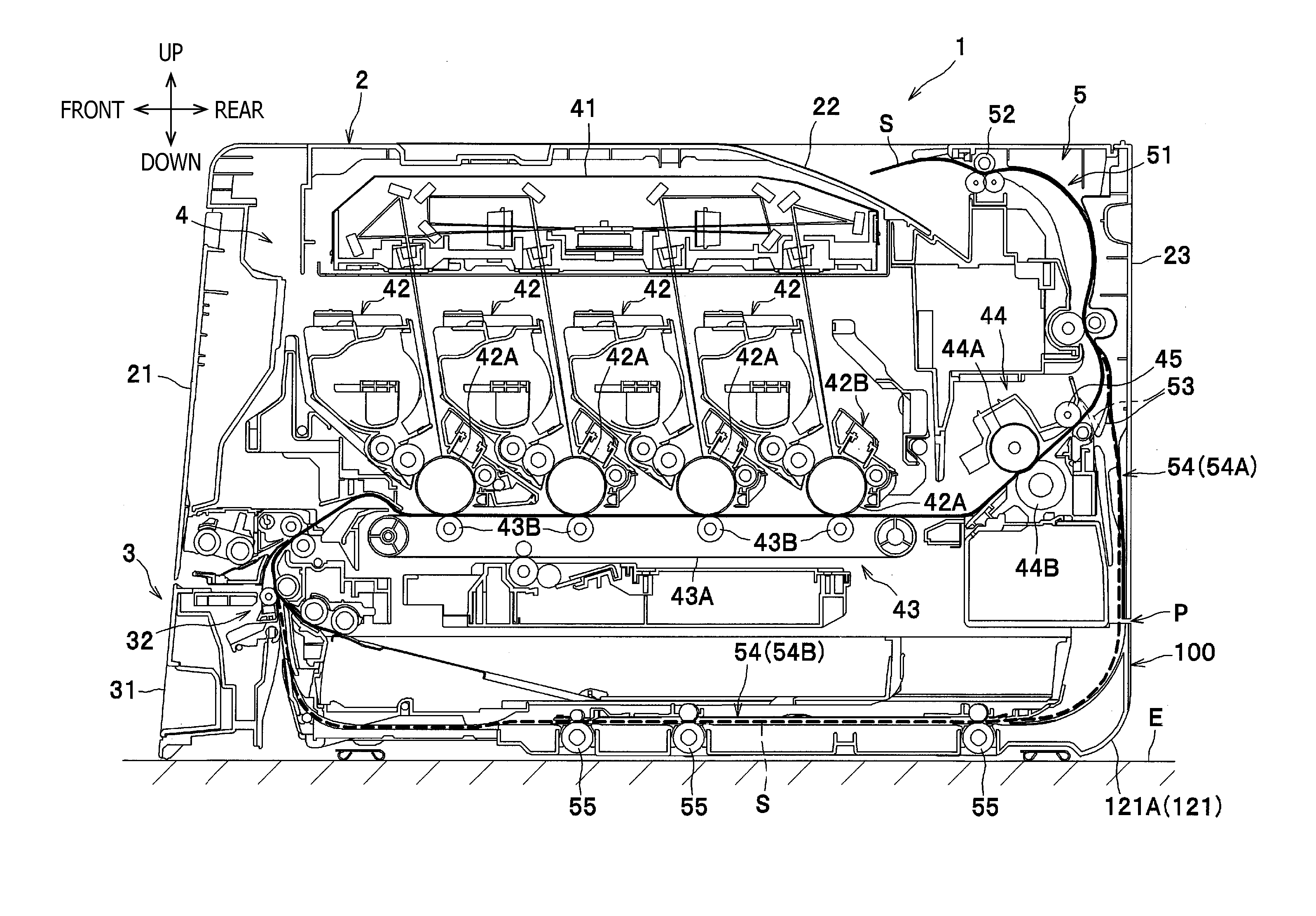
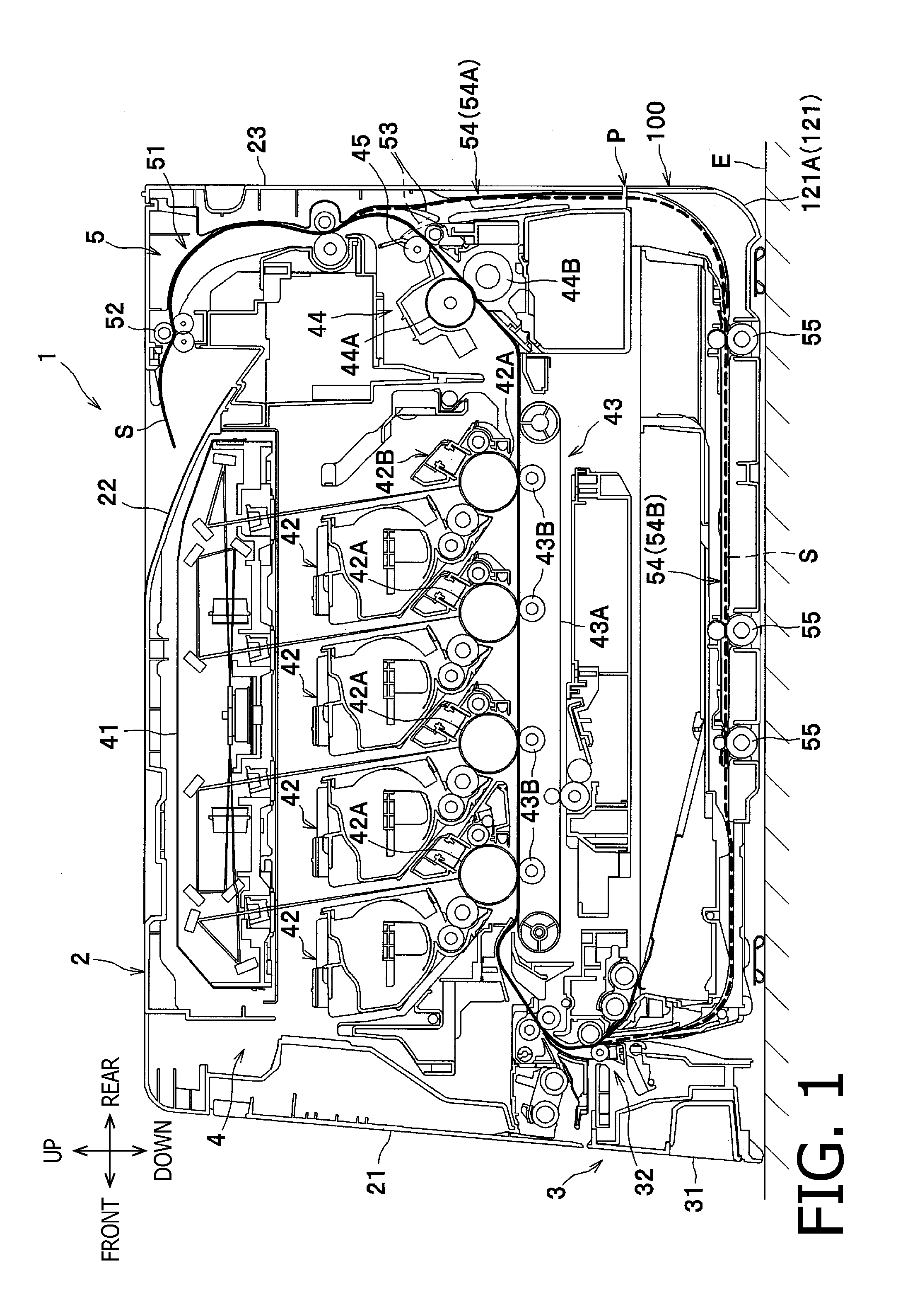
[0017]Hereinafter, a configuration of a color printer 1 according to an embodiment of the present invention will be described with reference to the accompanying drawings. In the present embodiment, directions concerning the color printer 1 will be referred to in accordance with orientation as indicated by arrows in each drawing. Therefore, for example, a viewer's left-hand side appearing in FIG. 1 is referred to as a front side of the color printer 1, and a right-hand side in FIG. 1 opposite from the front side is referred to as rear. A side which corresponds to the viewer's nearer side is referred to as left, and an opposite side from the left, which corresponds to the viewer's further side is referred to as right. The up-down direction in FIG. 1 corresponds to a vertical direction of the color printer 1. Further, the right-left direction of the color printer 1 may be referred to as a widthwise direction, and the front-rear direction may be referred to as a direction of depth. The ...


PUM


Abstract

An image forming apparatus is provided. The image forming apparatus includes an image forming unit, a return-sheet conveyer unit to convey a recording sheet carried from the image forming unit along a return-sheet path to return to the image forming unit, an upper frame unit including a pair of side frames to support the image forming unit in a position there-between, and a pair of lower frames arranged to have a predetermined amount of clearance there-between to have the return-sheet conveyer unit in the clearance, and configured to be less rigid than the upper frame unit and to support lower sections of the pair of side frames. A vertical position of the return-sheet conveyer unit with respect to the image forming unit is defined with reference to the upper frame unit by having a part of the return-sheet conveyer unit aligned to be in contact with the upper frame unit.

Description

CROSS REFERENCE TO RELATED APPLICATION[0001]This application claims priority from Japanese Patent Application No. 2010-098467, filed on Apr. 22, 2010, the entire subject matter of which is incorporated herein by reference.BACKGROUND[0002]1. Technical Field[0003]An aspect of the present invention relates to an image forming apparatus, which is capable of forming images on a recording sheet.[0004]2. Related Art[0005]A printer capable of forming images on either side of a sheet of recording medium (e.g., paper) is known. In order to have images formed on both sides of the sheets (i.e., double-face printing), for example, the printer may convey the sheet in an image forming unit to form an image on a first side of the sheet and further convey the sheet in a return-sheet conveyer unit, which conveys the sheet to return to the image forming unit in a reversed orientation so that an image is formed on a second side of the sheet.[0006]For another example, a printer having a lower frame, in ...

Claims


Application Information

Patent Timeline
IPC IPC(8): G03G15/00
CPCG03G15/234G03G15/6579B41J29/02G03G21/1619G03G2221/1678G03G2221/1684G03G15/6502B65H2402/40B65H2402/44B65H2402/32G03G2215/00383B65H2401/23
Inventor SOUDA, MAKOTO
Owner BROTHER KOGYO KK
Why Eureka
Try Eureka