Tower element

a technology of towers and elements, applied in the direction of rod connections, sustainable manufacturing/processing, final product manufacturing, etc., can solve the problems of increasing the size of towers, inability to transport via road networks, and increasing the cost of transportation solutions, so as to achieve a large degree of flexibility in these steps

Inactive Publication Date: 2010-12-23
ANDRESEN TOWERS
View PDF19 Cites 27 Cited by
  • Summary
  • Abstract
  • Description
  • Claims
  • Application Information

AI Technical Summary

Benefits of technology

[0009]By such a tower element there is achieved the great advantage and flexibility that production in the form of machining, surface treatment, transport and mounting of the individual segments can be performed in a much easier way than possible with tower elements which are welded together and finished in a factory. Compared with the closest prior art as described above, there is the great advantage of the solution according to the invention that in the overlap existing on the outer surface between two segments arranged in continuation of each other, a mechanical joining can be performed between the two segments in transverse direction. This mechanical joint between two segments results in a more stable construction and a rigidity substantially corresponding to the rigidity that may be achieved in segments joined by welding. A joint between segments without joining in transverse direction is less rigid, thus obviously providing a design which is exposed to larger deflections during operation. The mechanical joint may be designed such that very small movements between the two segments are allowed, or alternatively, the joint can be made as a fit joint that provides optimal rigidity in the joint.
[0011]During mounting of the segments, and also subsequently, the mechanical joint is relieved in the overlap on the outer surface in that the inwardly facing flanges are with a butt joint where an upper segment in principle rests on the downwardly facing flanges of the a lower segment. Simultaneously with achieving an advantageous joint and overlap between two segments, easy and secure mounting is thus also achieved as it is easy for the fitters to ascertain whether and that the segments are in correct position.
[0013]A tower element for a tower according to the invention may be where segments are joined with other and previously mounted segments in a tower element. Alternatively, one or more segments may be joined with one or more foundation segments. These foundation segments may be adapted for embedding in a concrete foundation or for mounting on a foundation of one or another suitable kind. Foundation segments may, for example, constitute a reinforcement of at least part of the lowermost part of the tower element. This may be achieved by making the foundation segments such that they constitute a reinforcement of the construction in that the material thickness is increased by tower element segments and the foundation segments overlapping each other by e.g. one, two, three metres, or more. In this way there can easily be made a reinforcement that allow for a door opening in the side of the tower.
[0020]Calculations of costs of towers constructed of segments as described here show that already at a tower height of about 60 metres it is cheaper to use this building principle as compared with welded towers. Moreover, the material thickness may in some cases be reduced from 48 mm to 16 mm, whereby obviously a lower material price is attained, but also a much easier handling during production as well as by mounting. If the segments are made in lengths of 12 to 18 metres, it is possible to transport them by usual transporting means and by lengths up to about 12 metres even in closed standard containers, and by longer segments in special containers. Another and very significant advantage is that the segments can be corrosion protected by galvanising, as the segments are no larger than they may be handled during the galvanisation process.

Problems solved by technology

Since nothing indicates that such towers for wind power plants will be smaller in the future, it is necessary with solutions that allow transport via the roads if not other and appreciably more expensive transport solutions are to be applied.
It is thus a fact that the size of these towers is increasing, and that it is not uncommon for the towers to have such a large diameter that transporting via the road network is no longer possible without dividing the individual tower elements into lesser sections.
Such tower elements still require much workshop time for rolling and welding and are furthermore cumbersome to transport as yet.
The reason for not joining the joints in horizontal direction mechanically is apparently due to the fact that on other prior art tower constructions there is the tradition that welded tower elements have a weakness in these joints.
The joints are exposed to fatigue loads which in time cause rupture in the horizontal weld seams.
Towers made according to this principle have some drawbacks, however.
Moreover, a tower element cannot be assembled on the ground which subsequently is hoisted in place on one or more already mounted tower sections, if the case is a conical tower as the joint faces are large in vertical direction.
This process may, however, be performed more easily by making cylindric towers, but still with great difficulty.

Method used


Image

  • Tower element
  • Tower element
  • Tower element

Examples


Embodiment Construction

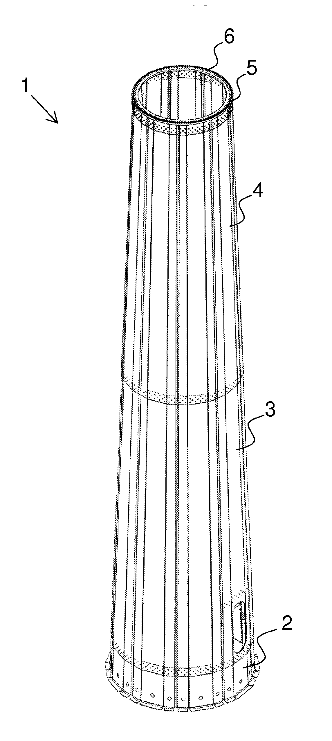
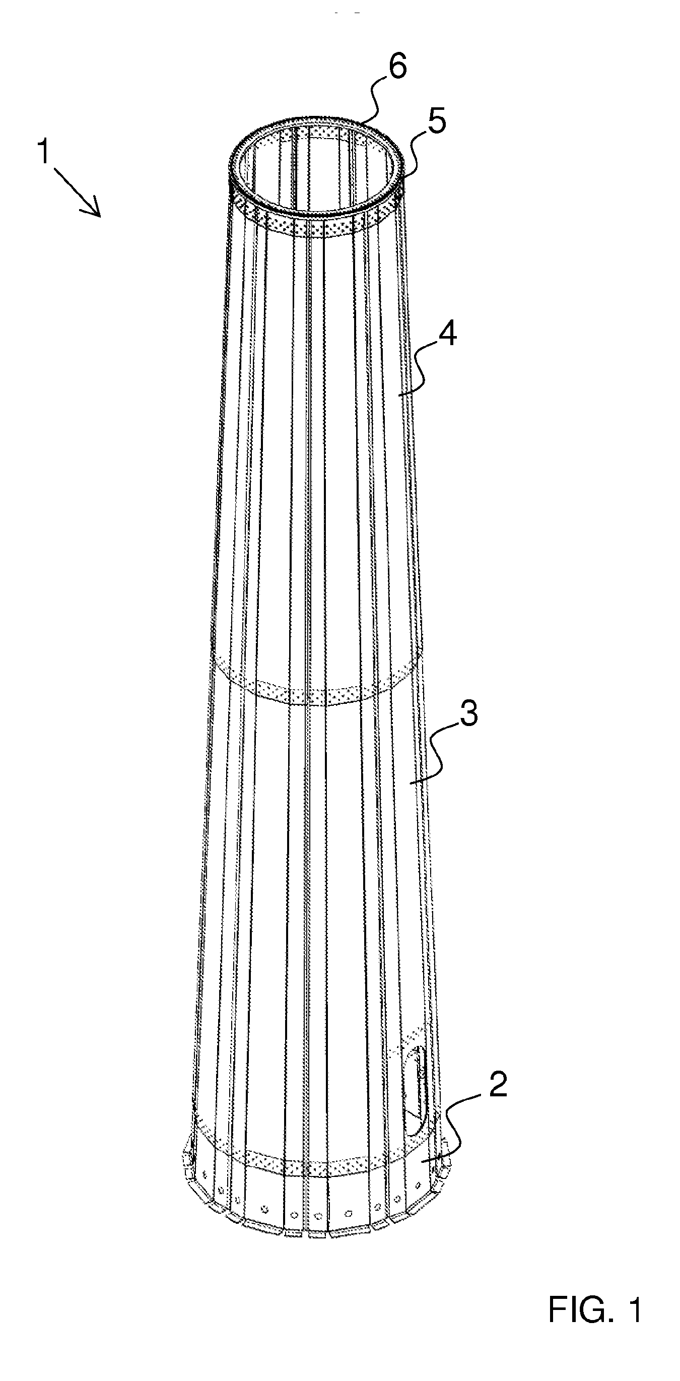
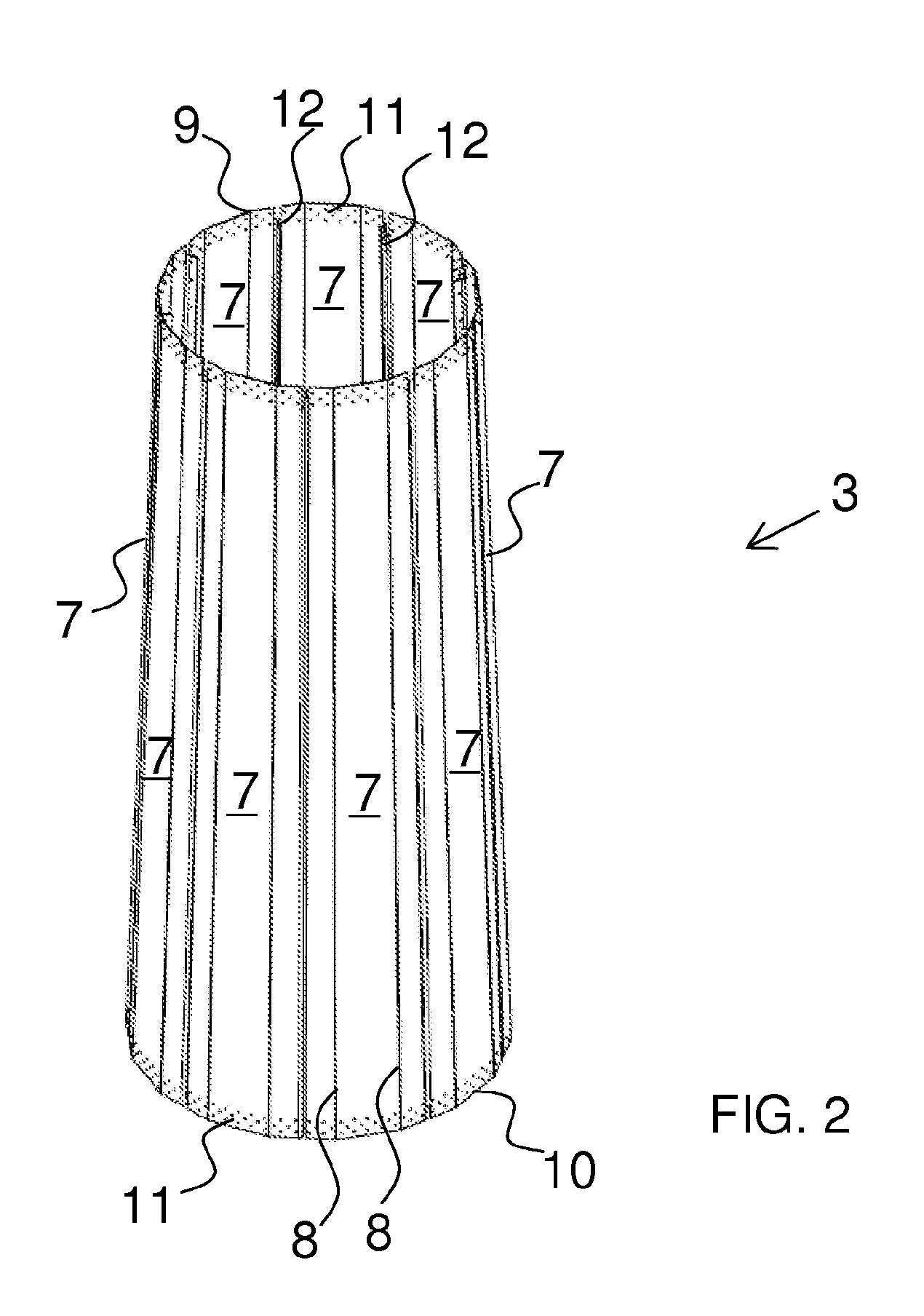
[0008]As mentioned above, the invention concerns a tower element for a tower, preferably for a wind power plant, where the periphery of the tower element is made up of a number of segments provided with inwardly facing flanges at the longitudinal sides for mounting to corresponding flanges on laterally arranged segments, where the individual segments are made with an overlap on the outer surface in the transverse joints and with a butt joint at the inwardly facing flanges.

[0009]By such a tower element there is achieved the great advantage and flexibility that production in the form of machining, surface treatment, transport and mounting of the individual segments can be performed in a much easier way than possible with tower elements which are welded together and finished in a factory. Compared with the closest prior art as described above, there is the great advantage of the solution according to the invention that in the overlap existing on the outer surface between two segments a...


PUM


Abstract

The invention concerns a tower element for a tower, preferably for a wind power plant, where several tower elements with an outer surface and an inner surface are mounted on top of each other, where the periphery of the tower element is made up of a number of segments provided with inwardly facing flanges at the longitudinal sides, the flanges being connected to corresponding flanges on laterally arranged segments. The individual segments are made with an overlap on the outer surface in the transverse joints and with a butt joint at the inwardly facing flanges. By the invention there is achieved flexibility in production and during transport and mounting. With an overlap on the outer surface between two segments, mechanical joining can be performed between two segments in transverse direction. This mechanical joint between two segments results in a more stable construction and a rigidity substantially corresponding to the rigidity that may be achieved in segments joined by welding.

Description

FIELD OF THE INVENTION[0001]The present invention concerns a tower element for a tower, preferably for a wind power plant, where several tower elements are mounted on top of each other, where the tower element has an outer surface and an inner surface, where the periphery of the tower element is made up of a number of segments preferably made of steel, where these segments are provided with inwardly facing flanges at the longitudinal sides, where these flanges are connected to corresponding flanges on laterally arranged segments, thus constituting a casing for a tower element.BACKGROUND OF THE INVENTION[0002]It is commonly known to use various types of tower designs for i.a. modern wind power plants. Through the years, different variants have been applied, e.g. lattice work designs; however, in recent years the most preferred have particularly been steel towers made with tubular shape. These are typically made in lengths that allow handling on common roads and mainly with common tra...

Claims


Application Information

Patent Timeline
Patent Type & Authority Applications(United States)
IPC IPC(8): E04H14/00E04H12/00
CPCE04H12/085F03D11/04Y10T403/635Y02E10/728F05B2240/40F03D13/22F03D13/20Y02P70/50Y02E10/72
Inventor KRYGER, ARNERYHOLL, LARS
Owner ANDRESEN TOWERS
Why Eureka
Try Eureka