Instrumentation and associated techniques for minimally invasive vertebral rod installation

a vertebral connecting element and instrumentation technology, applied in the field of spinal fixation surgery, can solve the problems of less than optimal spinal fixation, reduced nerve function, and debilitating pain, and achieve the effects of promoting patient recovery post-surgery, improving efficiency and accuracy, and minimal invasiveness

Active Publication Date: 2013-06-11
ZIMMER BIOMET SPINE INC
View PDF20 Cites 29 Cited by
  • Summary
  • Abstract
  • Description
  • Claims
  • Application Information

AI Technical Summary

Benefits of technology

[0008]As is common in many spinal fixation systems, vertebral anchors such as pedicle screws are inserted into the target vertebrae of a patient's spinal column. The spinal fixation system typically includes a connecting element joining at least two vertebral anchors to provide added support and a degree of rigidity to the patient's spine. The connecting element may be a rigid spine rod that is generally linear or shaped, as appropriate, or the connecting element may be a less rigid structure. Nevertheless, installation of the connecting element to the vertebral anchors coupled to the respective vertebrae is facilitated through a minimally invasive surgical procedure according to various embodiments of this invention.
[0015]The various embodiments of this invention enable the surgeon to install the spinal fixation construct with smaller discrete incisions as opposed to an extended incision. As such, a more minimally invasive surgical procedure can be accomplished with this invention thereby promoting patient recovery post-surgery. As a result of these and other aspects of this invention, increased efficiency and accuracy is provided for installation of a spinal fixation construct in a minimally invasive atmosphere thereby promoting patient recovery and optimum spinal surgery results.

Problems solved by technology

A variety of types of spinal column disorders may be caused by abnormalities, disease, trauma or the like and result in debilitating pain as well as diminished nerve function in many cases.
In combination with the relatively long incision typically required for the installation of the fixation construct, extended surgical procedures and related difficulties or complications are generally recognized as major contributing influences for extended patient recovery and less than optimal spinal fixation results.

Method used


Image

  • Instrumentation and associated techniques for minimally invasive vertebral rod installation
  • Instrumentation and associated techniques for minimally invasive vertebral rod installation
  • Instrumentation and associated techniques for minimally invasive vertebral rod installation

Examples


Embodiment Construction

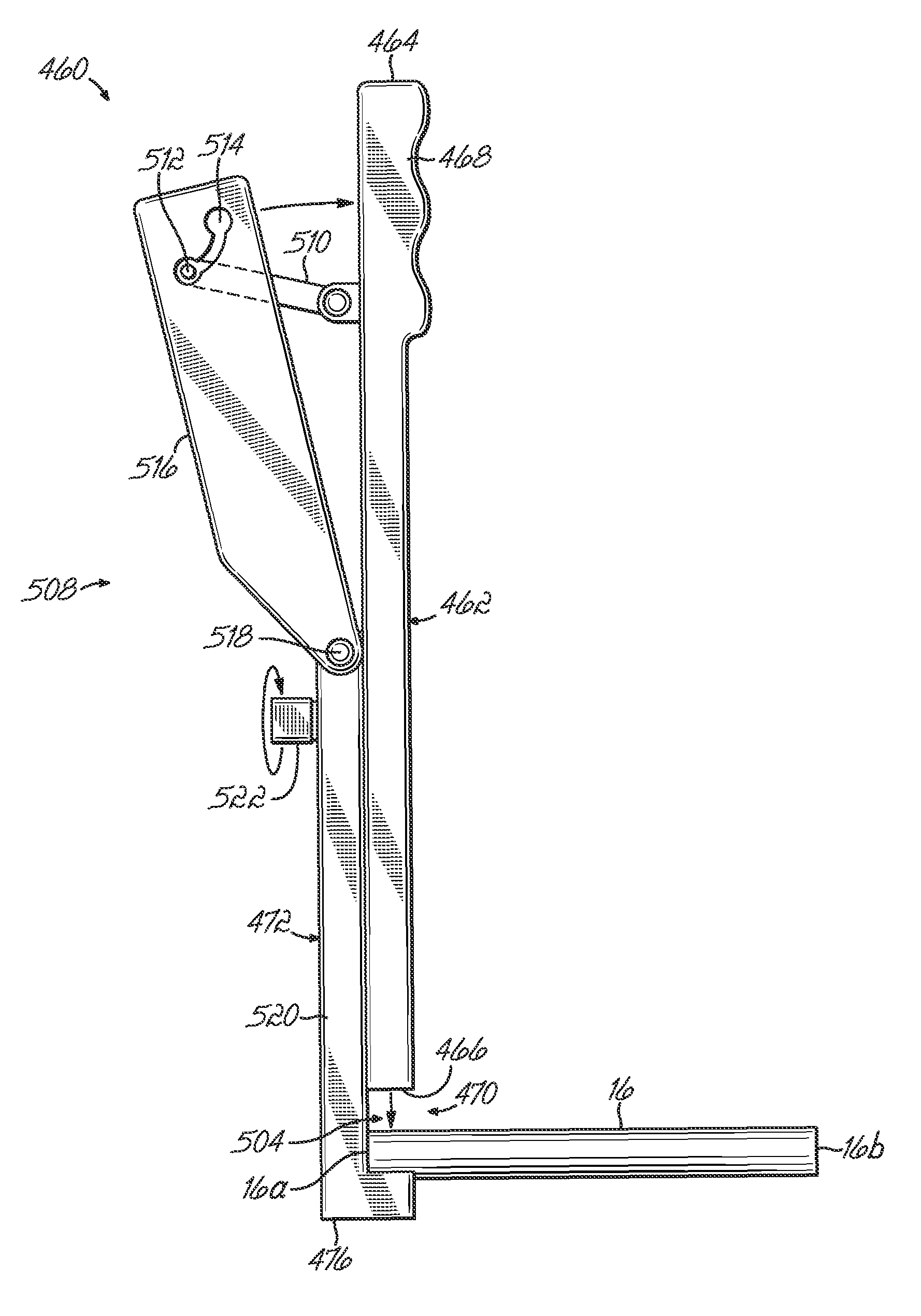
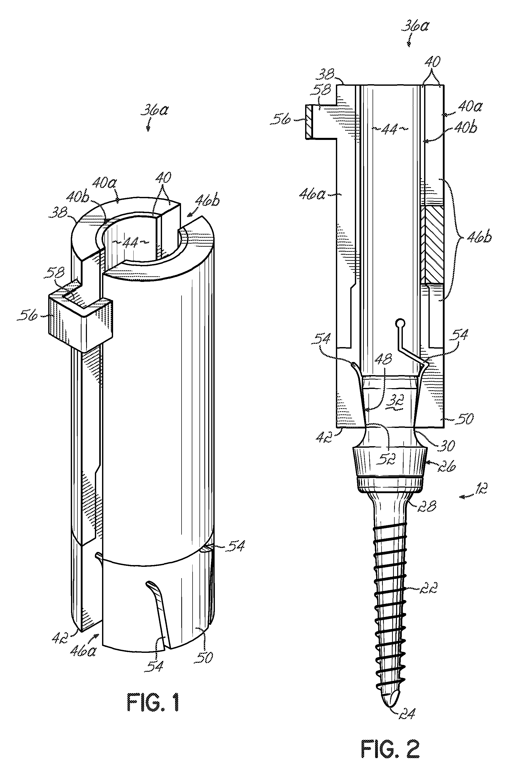
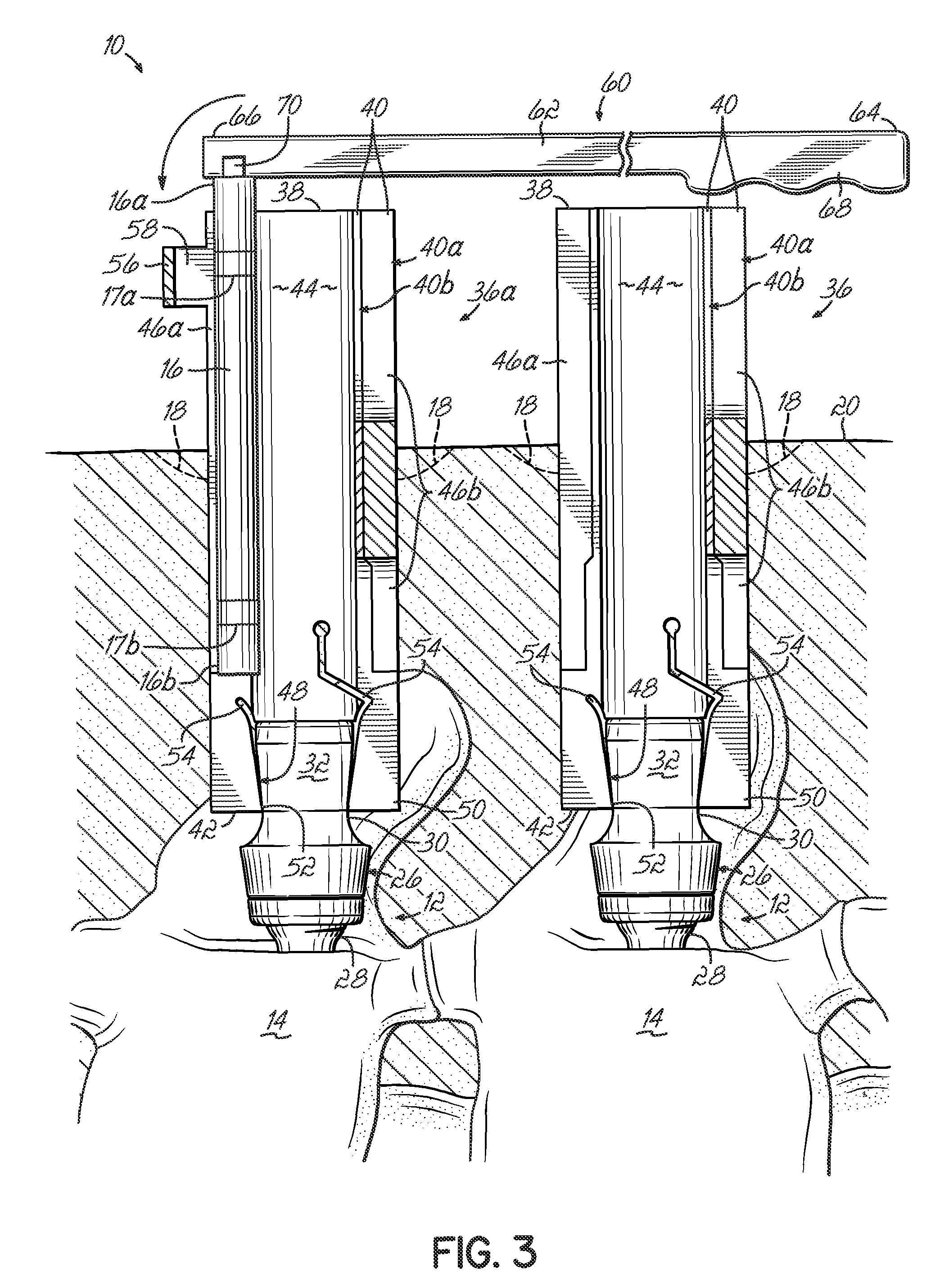
[0035]Referring to the drawings, various embodiments of spine rod or connecting element installation tools to assist in a minimally invasive surgery to install a spinal fixation construct and associated installation methods are shown. In FIG. 3, an exemplary spinal fixation construct 10 includes a number of vertebral anchors 12 which in one embodiment are each pedicle screw assemblies, each of which is inserted into selected vertebrae 14 of a patient. The pedicle screw assemblies 12 are joined together in the spinal fixation construct by a connecting element 16 which in one embodiment is a spine rod. The connecting element 16 may be something other than a rigid rod according to alternative embodiments of this invention. According to various aspects of this invention, the individual pedicle screw assemblies 12 may be inserted into the patient through discrete and often individual incisions 18 in the patient's skin 20. In certain instances, a single incision 18 such as a minimally inv...


PUM


Abstract

Spinal fixation systems may be installed utilizing instruments and techniques alone or in combination with selectively attached extension members mounted on vertebral anchors to extend percutaneously from the spine. The surgical procedures associated with this invention involve making small, discrete incisions for the placement of select vertebral anchors. The extension members retract soft tissue, muscle and the like to thereby provide visibility and access to the head of the anchor. Instrumentation is utilized to deliver and install components such as a spine rod, set screw and other required hardware to the anchors. Once a spine rod or other components are secured to the pedicle screws, the instrumentation and extension members are removed from the patient.

Description

BACKGROUND[0001]This invention relates generally to spinal fixation surgery and more specifically relates to instrumentation and associated techniques for minimally invasive installation of vertebral connecting elements of spinal fixation constructs.[0002]The human spinal column is a highly complex system of bones and connected tissues that provide support for the body and protects the delicate spinal cord and nerves. The spinal column includes a series of vertebrae stacked one atop the other. Each vertebral body includes a relatively strong cortical bone portion forming the outside surface of the body and a relatively weak cancellous bone portion forming the center of the body. An inter-vertebral disc is situated between each vertebral body that provides for cushioning and dampening of compressive forces applied to the spinal column. The vertebral canal containing delicate spinal cords and nerves is located just posterior to the vertebral bodies.[0003]A variety of types of spinal c...

Claims


Application Information

Patent Timeline
Patent Type & Authority Patents(United States)
IPC IPC(8): A61B17/70
CPCA61B17/7085A61B17/7089
Inventor HESTAD, HUGH D.KUESTER, W. MATTHEW
Owner ZIMMER BIOMET SPINE INC
Why Eureka
Try Eureka