
Wearable Material Handling System

a technology of material handling and wearable parts, which is applied in the direction of programmed manipulators, travelling articles, travelling sacks, etc., can solve the problem of not providing a means enabling users to support front load

Active Publication Date: 2011-11-03
RGT UNIV OF CALIFORNIA +1
View PDF5 Cites 138 Cited by
  • Summary
  • Abstract
  • Description
  • Claims
  • Application Information

AI Technical Summary

Problems solved by technology

Although useful to aid a user in walking or carrying a backpack, the above-references do not provide a means enabling a user to support a front load utilizing an exoskeleton to reduce the energy expended by the user.

Method used


Image

  • Wearable Material Handling System
  • Wearable Material Handling System
  • Wearable Material Handling System

Examples


Embodiment Construction

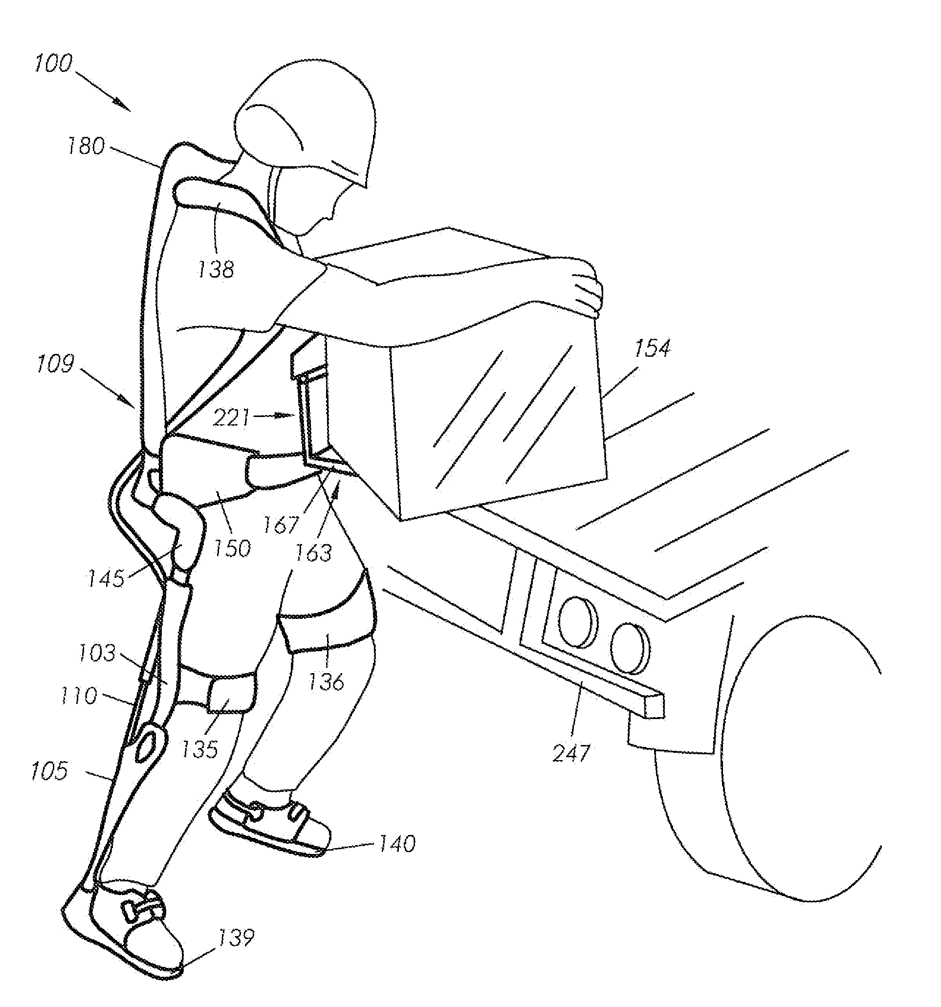
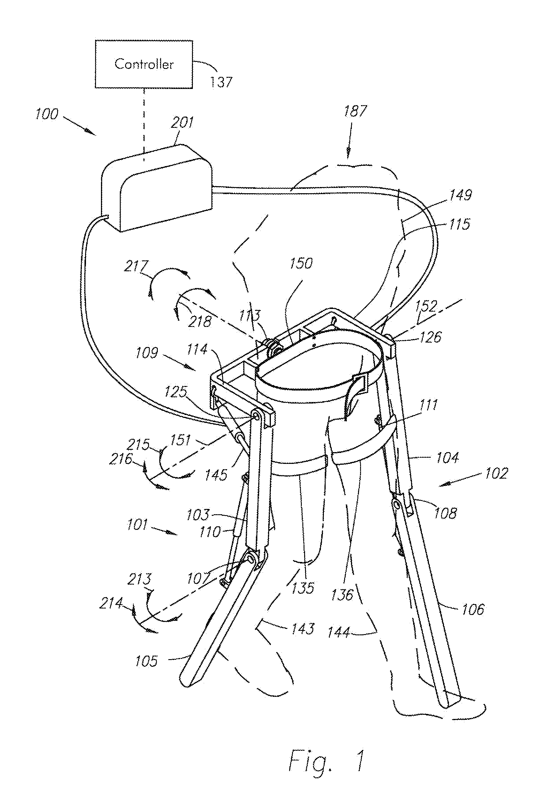
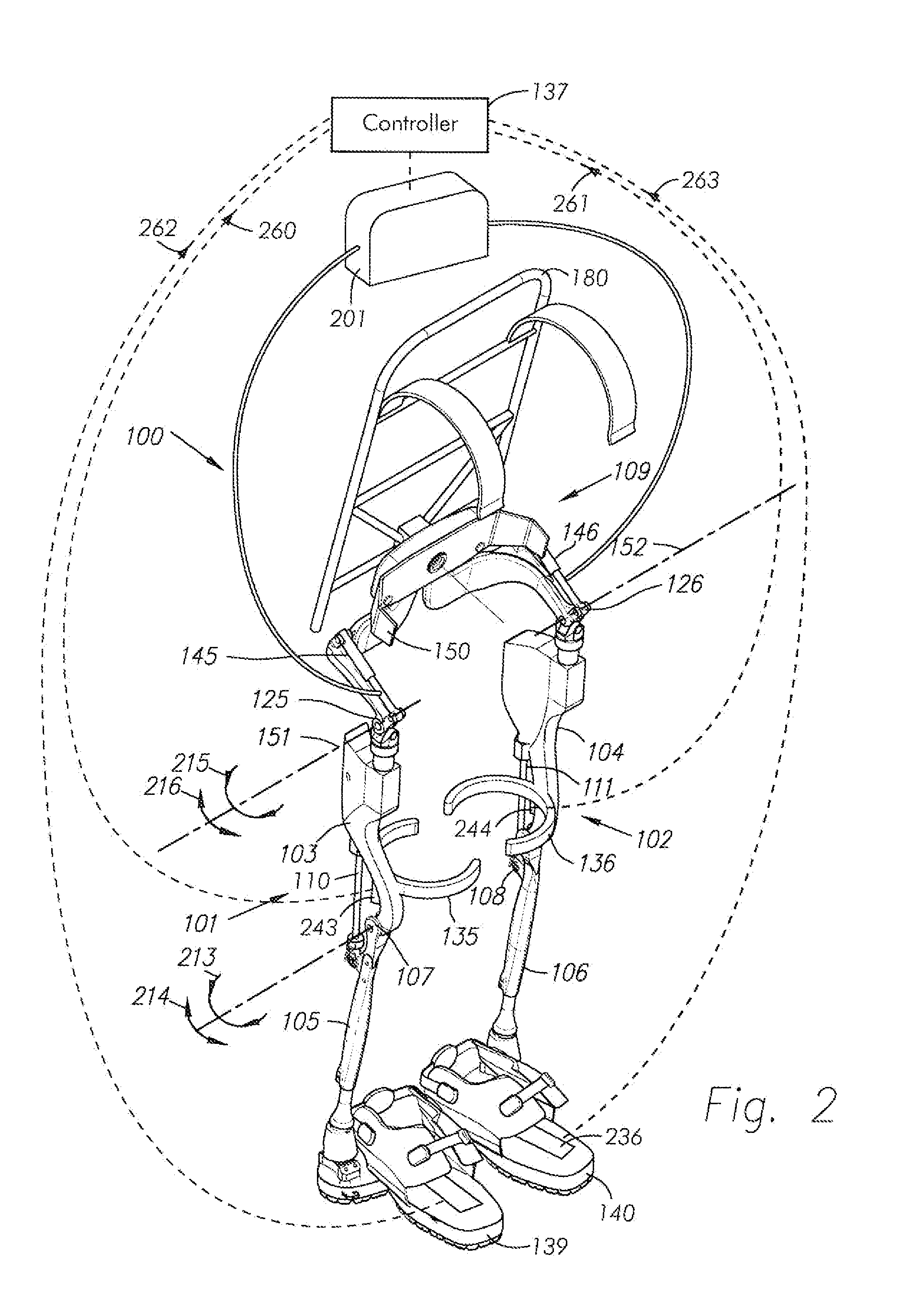
In accordance with one embodiment of the present invention, FIG. 1 is a perspective drawing illustrating a lower extremity exoskeleton 100 which is wearable by a person indicated at 187. Lower extremity exoskeleton 100, in addition to other components, includes two leg supports 101 and 102, which are configured to be coupled to a person's respective lower limbs 143 and 144 and configured to rest on the ground, or a support surface, during a stance phase. The leg supports 101 and 102, in addition to other components, include respective thigh links 103 and 104, and shank links 105 and 106. Two knee joints 107 and 108 are configured to allow flexion (indicated by arrow 213) and extension (indicated by arrow 214) between the respective shank and thigh links 103 and 105 and 104 and 106 of leg supports 101 and 102 during a corresponding leg support swing phase. In some embodiments, knee joints 107 and 108 are configured to resist flexion between the respective shank and thigh links 103, 1...


PUM


Abstract

An exoskeleton configured to be coupled to a person includes an exoskeleton trunk and leg supports adapted to contact the ground. Hip torque generators extend between the exoskeleton trunk and respective leg supports. A load holding mechanism is rotatably coupled to the exoskeleton trunk, preferably via over-shoulder members configured to support a load in front of the person. In use, hip torque generators create torque between the exoskeleton trunk and respective leg supports in the stance phase, wherein at least one torque generator is configured to create a first torque between the exoskeleton trunk and one of the first and second leg supports in the stance phase opposing a second torque generated on the exoskeleton by a weight of the load. Load bearing sensors may be utilized to determine the torque generated by the load and communicate with a controller to control power to the torque generators.

Description

BACKGROUND OF THE INVENTION1. Field of the InventionThe present invention relates generally to the field of material handling systems and, more particularly, to the field of lower extremity exoskeletons that are worn by their wearers and allow for carrying heavy loads in front of their wearers.2. Discussion of the Prior ArtIn general, it is known in the art to provide orthotic devices to aid a person in walking or carrying a load. One example, such as set forth in U.S. Patent Application Publication No. 2007 / 0056592, provides an exoskeleton including a power unit to provide power to torque generators connecting a thigh link of the exoskeleton with a shank link of the exoskeleton. The '592 publication basically addresses providing power to a knee portion of an exoskeleton. In another example set forth in U.S. Patent Application Publication No. 2007 / 0123997, an exoskeleton worn by a human includes a hip joint having a passive spring or an actuator to assist in lifting an exoskeleton a...

Claims


Application Information

Patent Timeline
Patent Type & Authority Applications(United States)
IPC IPC(8): A45F3/00
CPCB25J9/0006
Inventor KAZEROONI, HOMAYOONHARDING, NATHANANGOLD, RUSSDONAMUNDSON, KURTBURNS, JON WILLIAMZOSS, ADAM
Owner RGT UNIV OF CALIFORNIA
Learn More