Method and apparatus for reading and controlling electric power consumption

Active Publication Date: 2005-05-05
TRENDPOINT SYST
View PDF99 Cites 176 Cited by
  • Summary
  • Abstract
  • Description
  • Claims
  • Application Information

AI Technical Summary

Benefits of technology

[0008] The photoelectric sensor beams a light onto a rotating disk, visible on the face of the meter, whose surface reflects the light. A marker such as a black dot or line placed on the rotating disk absorbs the beamed light resulting in an interval where a lower level of light is being reflected. The photoelectric sensor counts these intervals, representing the number of turns the disk rotates indicating utility usage during a given time period. The apparatus connects to

Problems solved by technology

However, the majority of methods using optical light-sensing devices are installed inside the existing meter and/or require professional installation.
This process is inefficient and also very costly for either the utility company or the consumer.
A significant disadvantage typical of these devices is that the installation process requires the existing meter to be physically opened and/or the optical light sensing arrangement to be assembled with professional assistance.
Thus, an ordinary consumer generally cannot set up the device, and therefore consumers would have to bear installation costs.
However, the device requires the angle and heights of the light source and sensor to be adjusted in a specific manner using a height adjustment carrier having a collar that must be tightened, which a typical cus

Method used


Image

  • Method and apparatus for reading and controlling electric power consumption
  • Method and apparatus for reading and controlling electric power consumption
  • Method and apparatus for reading and controlling electric power consumption

Examples


Embodiment Construction

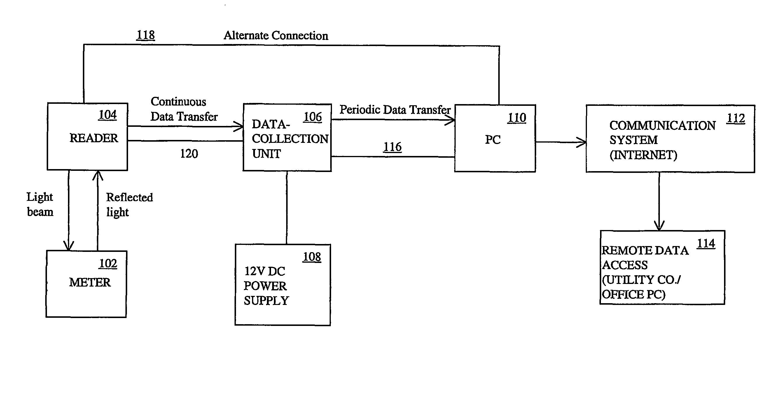
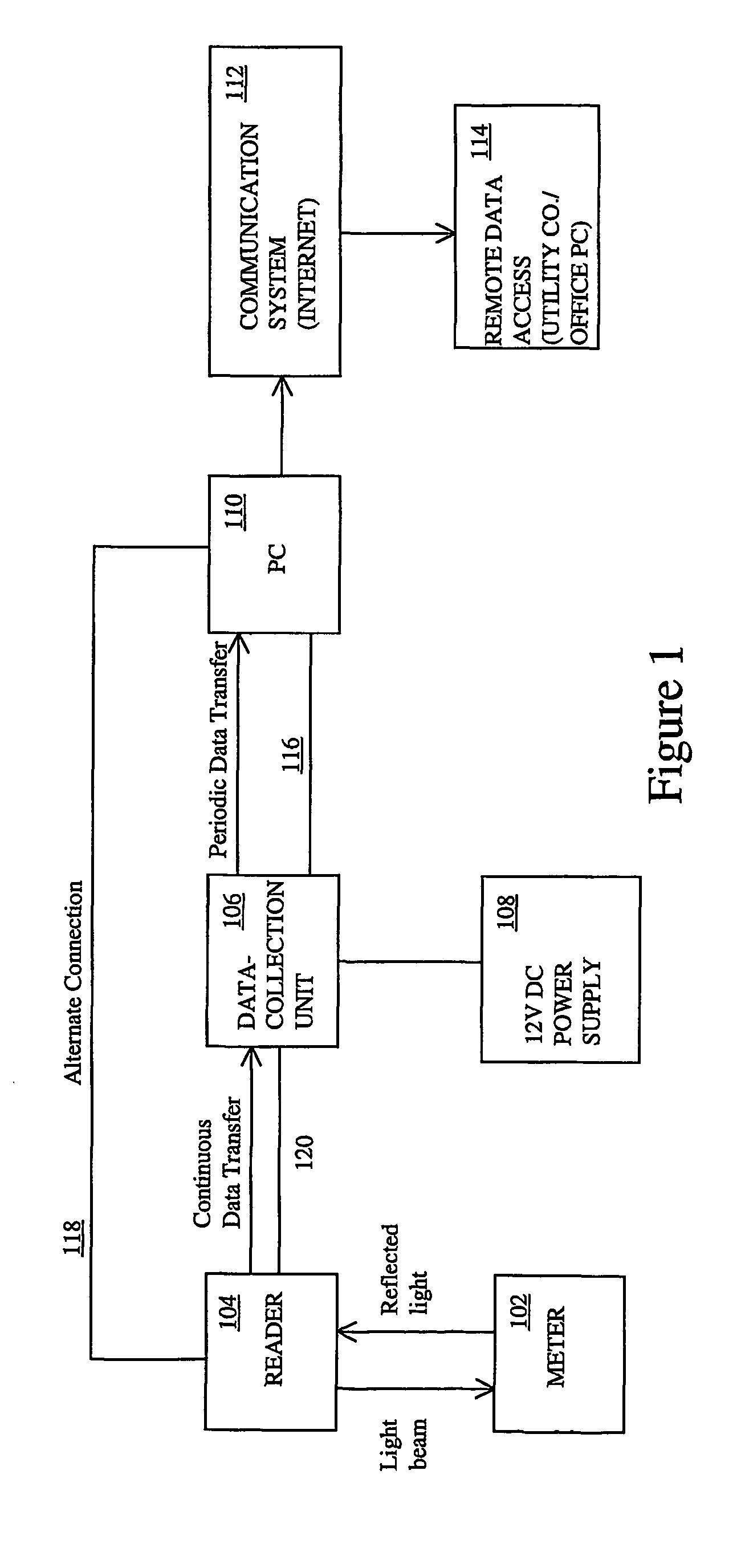
[0023]FIG. 1 illustrates a block schematic diagram of an apparatus 100 for reading and managing power consumption in accordance with the present invention. As shown in FIG. 1, a reader 104 is attached to a typical utility meter 102 such as an analog or digital power meter commonly found on homes, apartment buildings and commercial buildings. The reader 104 provides a means for automatically reading power consumption and may eliminate the need for manually reading the meter 102. The data generated by the reader 104 may be continuously transferred through a connection such as a serial cable 120, to a data collection unit 106 or alternatively directly to the monitoring device 110, such as a computer.

[0024] The data collector 106 is therefore optional. When provided, the data collection unit stores data generated by the reader 104. The data collection unit 106 may store data for a limited time when the monitoring device (computer) 110 is shut off or in the event of a power failure. Wit...


PUM


Abstract

An electro-optical, automatic meter reader for enabling a consumer to view and manage power consumption through a browser. A sensor attached to a bracket is mounted to the outside cover of a utility meter without modification of the meter or removal of its housing. A data-collector stores data obtained from the sensor via a serial port which may also provide power for the sensor, thus avoiding use of a dedicated power supply. The data-collector connects to a computer which provides a centralized object through which to view and manage power consumption. The real-time and combined historic data can be used to forecast whether usage will fall above or below a predetermined usage level at the end of a given period of time. In response to a forecast exceeding the level, the computer displays the appropriate graph in a red colored bar within a quantity vs. time chart. The computer may control power consuming devices. A communication system may be established to the system for remote management by the consumer or by the utility company for its own billing and management purposes.

Description

FIELD OF THE INVENTION [0001] This invention relates generally to a utility usage measurement system, and more particularly to a means of obtaining real-time utility consumption readings and also managing utility consumption by controlling end-use devices from the computer or personal digital assistant (PDA) of the consumer. BACKGROUND OF THE INVENTION [0002] There are various types of automatic meter reading devices (AMR) which use optical light-sensing arrangements to provide remote utility readings for determining utility consumption and for billing purposes. These devices were typically developed as a cost-effective alternative to the existing meter reading methods and devices. For example, these AMR devices avoid having a person walk or drive from establishment to establishment and manually read each meter. However, the majority of methods using optical light-sensing devices are installed inside the existing meter and / or require professional installation. Thus, a skilled or tra...

Claims


Application Information

Patent Timeline
IPC IPC(8): G01D4/00G01R21/133G01R22/06H02J3/00H02J13/00
CPCG01D4/004G01D4/008G01R21/133G01R22/063H02J3/008H02J13/001Y04S50/10Y02B90/247Y04S20/322Y04S20/50Y02B90/244Y04S20/327Y04S20/46Y02B90/242H02J13/00001H02J2310/12H02J13/00017H02J13/00004Y02B90/20Y04S20/30Y04S40/124Y02E60/00
Inventor HUNTER, ROBERT R
Owner TRENDPOINT SYST
Why Eureka
Try Eureka