Unmanned Flying Vehicle Made With PCB

a flying vehicle and unmanned technology, applied in the direction of vehicle position/course/altitude control, process and machine control, instruments, etc., can solve the problems of difficult assembly, reduced flight efficiency, complicated flying vehicle structure, etc., to simplify the structure of the flying vehicle, and minimize the effect of the entire siz

Inactive Publication Date: 2012-03-08
DREAM SPACE WORLD CORP
View PDF22 Cites 178 Cited by
  • Summary
  • Abstract
  • Description
  • Claims
  • Application Information

AI Technical Summary

Benefits of technology

[0022]According to the exemplary embodiments of the present invention, the structure of the unmanned flying vehicle can be simplified and the entire size can be minimized by installing constituent modules installed in the main board of the body portion and diversely installing other modules in the frame portion.
[0023]In addition, the frame portion is formed with a PCB so that wired cables between the constituent modules in the main board and the modules diversely formed in the frame portion can be eliminated, thereby simplifying the structure of the unmanned flying vehicle.
[0024]Further, as the frame portion is formed with a PCB, the frame portion is light-weighted so that it can fly with a small impellent force and accordingly various types...

Problems solved by technology

Such a structure of the unmanned flying vehicle increases the weight of the flying vehicle such that a flight efficiency is decreased, and the weight increase causes the main board, the battery, and the propeller to be enlarged, and accordingly the structure of the flying vehicle is complicated, difficult to be assembled, and production cost of the flying vehicle can be increased.
The unmanned flying vehicle of FIG. 1 has unlimited applicable ranges, but all electron modules are collected in the main board 10 at the center thereof so that the size of the main board 1...

Method used


Image

  • Unmanned Flying Vehicle Made With PCB
  • Unmanned Flying Vehicle Made With PCB
  • Unmanned Flying Vehicle Made With PCB

Examples


Embodiment Construction

[0035]The present invention will be described more fully hereinafter with reference to the accompanying drawings, in which exemplary embodiments of the invention are shown.

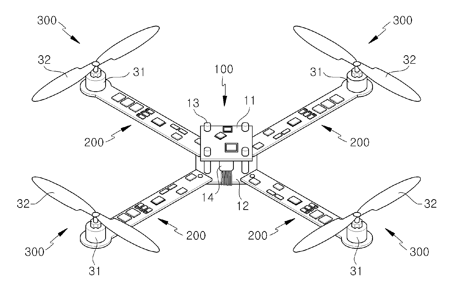
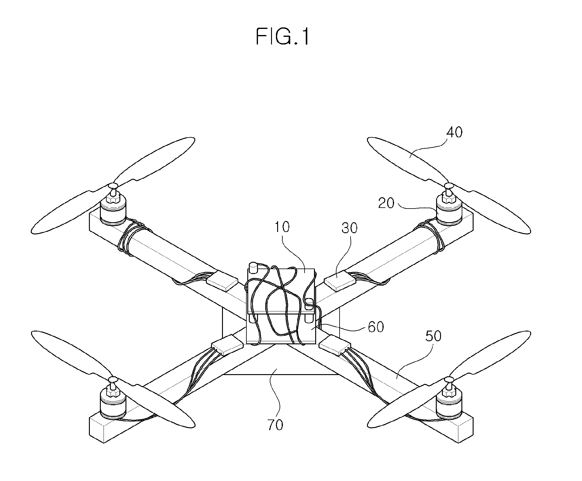
[0036]In the specification, “unmanned flying vehicle” refers to a flying vehicle that can be remotely controlled by a person without boarding thereon, and in further detail, it includes a trirotor having three propellers, a quadrotor having four propellers, a pentarotor having five propellers, a hexarotor having six propellers, and an octorotor having eight propellers. Thus, the quadrotor will be exemplarily described for convenience of description, but the present invention is not limited thereto, and it may be variously modified according to the number and configuration of the propellers.

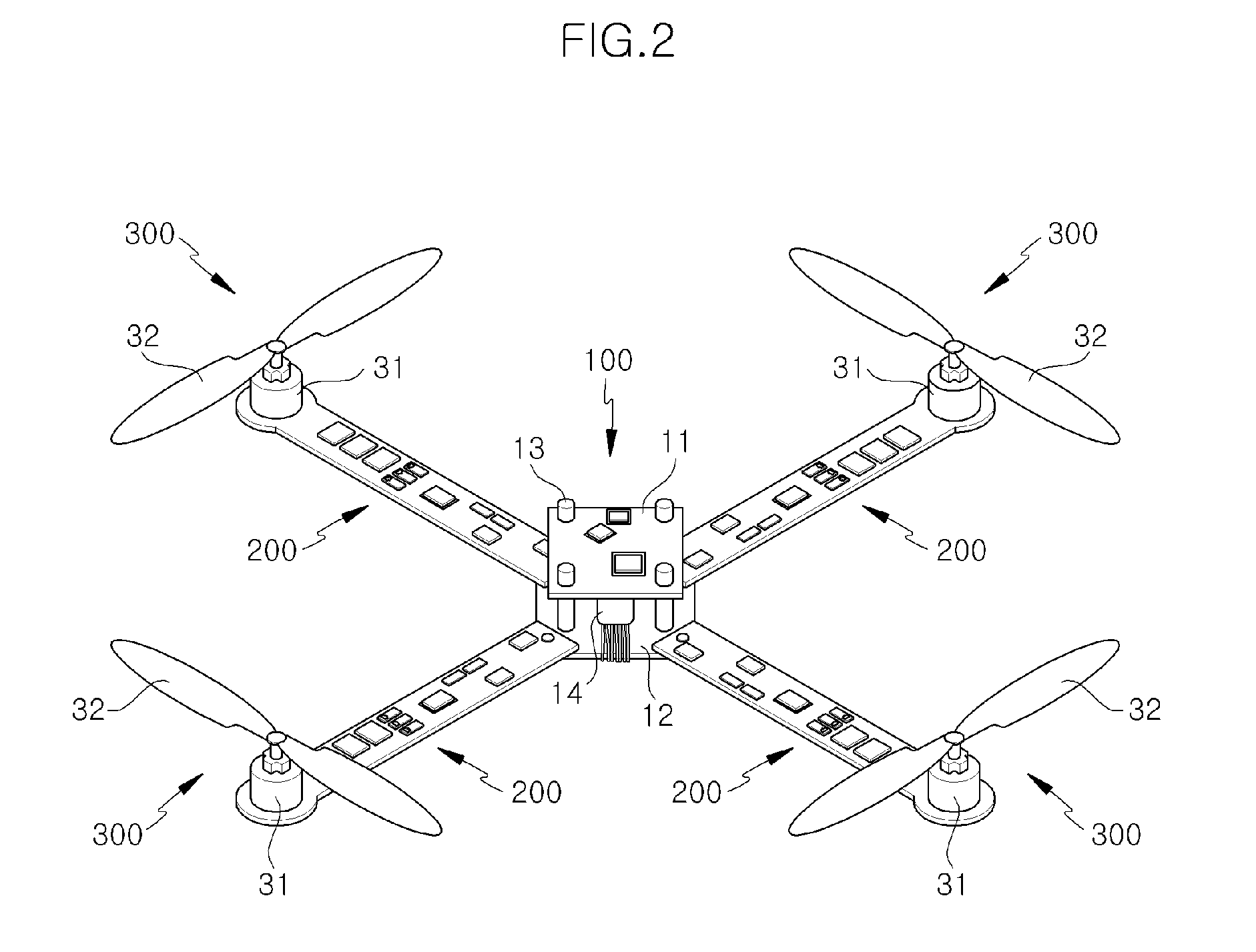
[0037]FIG. 2 illustrates a structure of an unmanned flying vehicle according to an exemplary embodiment of the present invention.

[0038]The unmanned flying vehicle shown in FIG. 2 includes a body portion 100, four frame portions ...


PUM


Abstract

The present invention relates to an unmanned flying vehicle using a PCB including a main board controlling power supply and flying operation, a motor rotating a propeller by changing electric energy into mechanical energy, a PCB frame changing a signal from a remote controller and connecting the main board with the motor, a propeller generating an impellent force by from rotation by the motor, a receiver receiving a control signal of the remote controller, and a remote controller controlling a motor rotation speed of a quadrotor and direction change, and accordingly, the structure of the unmanned flying vehicle can be simplified so that the flying vehicle can be down-sized and light-weighted, and assemblability can be improved.

Description

CROSS-REFERENCE TO RELATED APPLICATION[0001]This application claims priority to and the benefit of Korean Patent Application No. 10-2010-0086052 filed in the Korean Intellectual Property Office on Sep. 2, 2010, the entire contents of which are incorporated herein by reference.BACKGROUND OF THE INVENTION[0002](a) Field of the Invention[0003]Exemplary embodiments of the present invention relate to an unmanned flying vehicle that can reduce its size or weight and production cost by realizing a structure of the vehicle using a PCB for electronic parts installation.[0004](b) Description of the Related Art[0005]Recently, the need of an unmanned flying vehicle in an environment where a person feels difficult to work has been increased. The need of an unmanned flying vehicle in an environment where The unmanned flying vehicle has been applied to wide areas, for example, the flying vehicle can acquire video images in an unapproachable disaster area in the air, test power lines, or provide co...

Claims


Application Information

Patent Timeline
IPC IPC(8): G05D1/00B64C25/32B64C25/02B64C1/00B64C39/00
CPCB64C25/32B64C39/024B64C2201/108B64C2201/042B64C2201/027B64U50/19B64U30/29B64U20/83B64U10/14B64U20/60B64U30/299B64U10/13B64U30/20
Inventor RHEE, SUNG HOLEE, YONG SEUNG
Owner DREAM SPACE WORLD CORP
Why Eureka
Try Eureka