
Endoscopic ultrasonic surgical aspirator for use in fluid filled cavities

Active Publication Date: 2007-07-12
INTEGRA LIFESCI IRELAND
View PDF5 Cites 167 Cited by
  • Summary
  • Abstract
  • Description
  • Claims
  • Application Information

AI Technical Summary

Benefits of technology

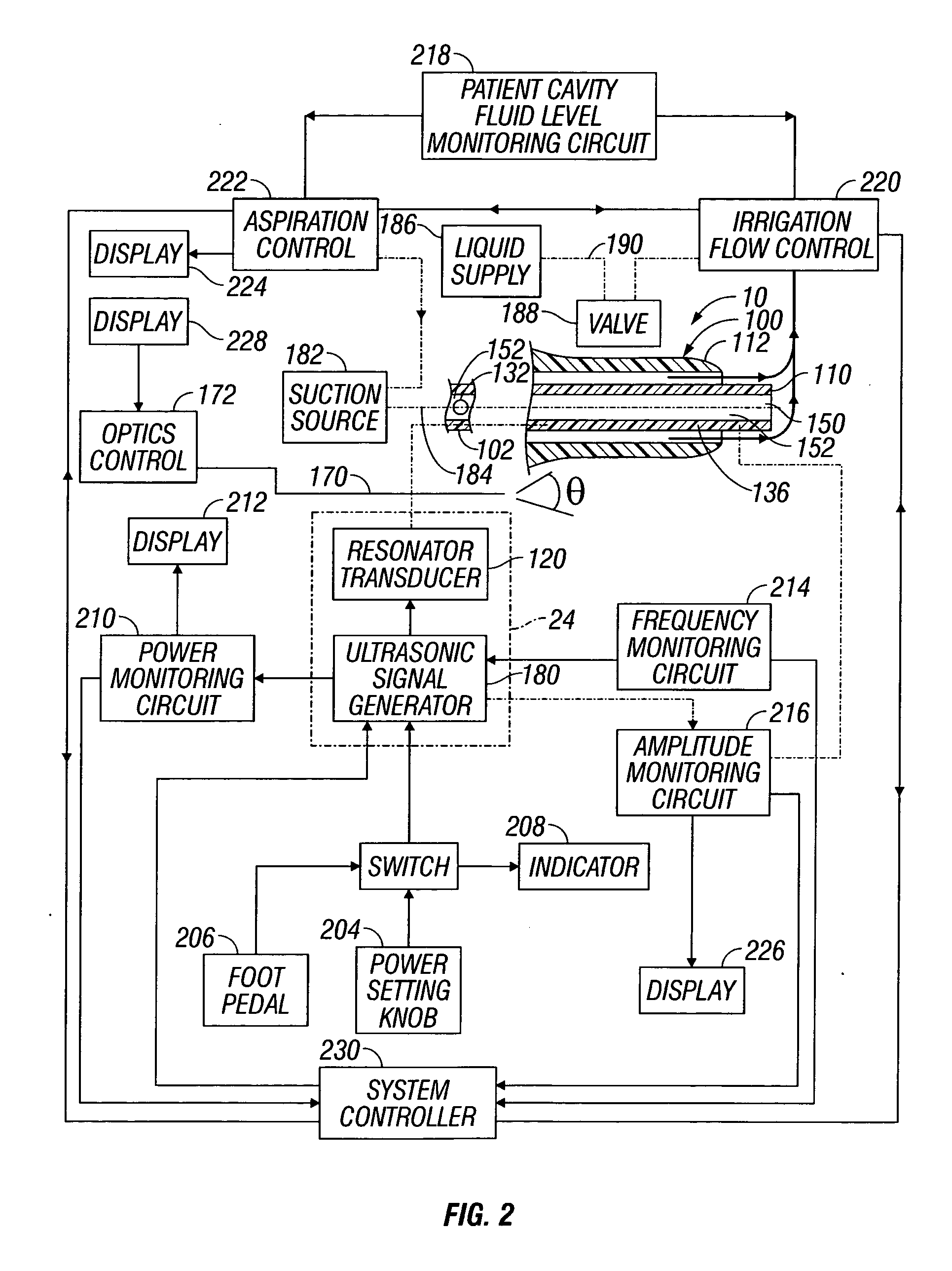
[0008] It is an object of the present disclosure to provide an ultrasonic horn having circuitry which controls power, frequency and amplitude of the tip of the ultrasonic horn occurring as a result of operation of a source of ultrasonic signal generating power controls either or both the supply of irrigation fluid and the suction aspiration so as to minimize damping of vibration of the tip of the ultrasonic horn.
[0020] It is envisioned that the circuitry controlling at least one of power, frequency and amplitude of the tip of the ultrasonic horn occurring as a result of operation of the source of ultrasonic signal generating power controls at least one of the supply of irrigation fluid and the suction aspiration so as to minimize damping of vibration of the tip of the ultrasonic horn.
[0026] It is envisioned that the steps of controlling the supply of irrigation fluid via monitoring of fluid level in a patient cavity during a surgical procedure and controlling the suction aspiration via monitoring of fluid level in the patient cavity during the surgical procedure may be performed by coordinating with the controlling of at least one of power, frequency and amplitude of the tip of the ultrasonic horn occurring as a result of operation of a source of ultrasonic signal generating power to the ultrasonic horn so as to minimize damping of vibration of the tip of the ultrasonic horn.

Problems solved by technology

If fluid fills a flue around an ultrasonic tip or is aspirated without air inside of the tip, the energy loss renders the tip inoperative.
Such conditions are most severe when an ultrasonic tip is used in environments such as a ventricle of the brain.

Method used


Image

  • Endoscopic ultrasonic surgical aspirator for use in fluid filled cavities
  • Endoscopic ultrasonic surgical aspirator for use in fluid filled cavities
  • Endoscopic ultrasonic surgical aspirator for use in fluid filled cavities

Examples


Embodiment Construction

[0031] Embodiments of the presently disclosed ultrasonic horn will now be described in detail with reference to the drawings, in which like reference numerals designate identical or corresponding elements in each of the several views. As used herein, the term “distal” refers to that portion of the instrument, or component thereof which is further from the user while the term “proximal” refers to that portion of the instrument or component thereof which is closer to the user.

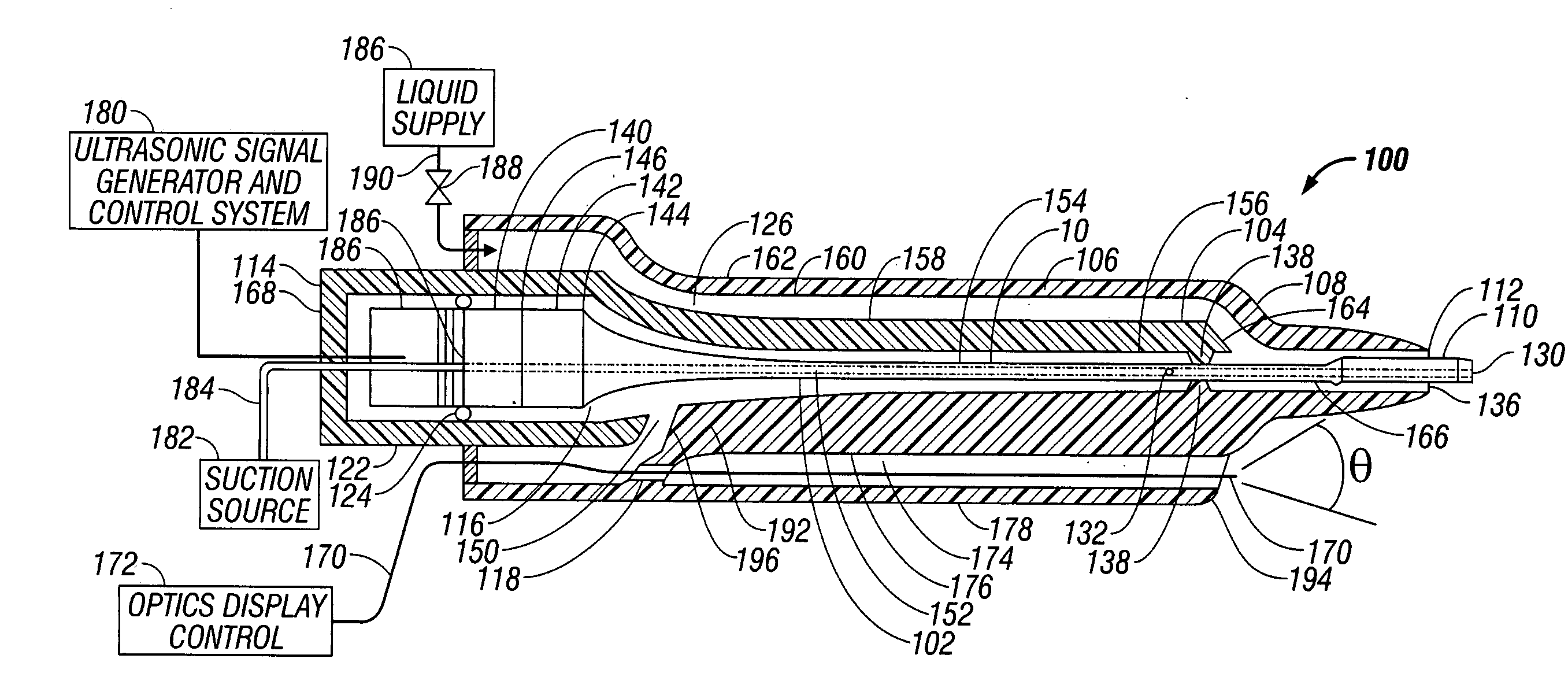
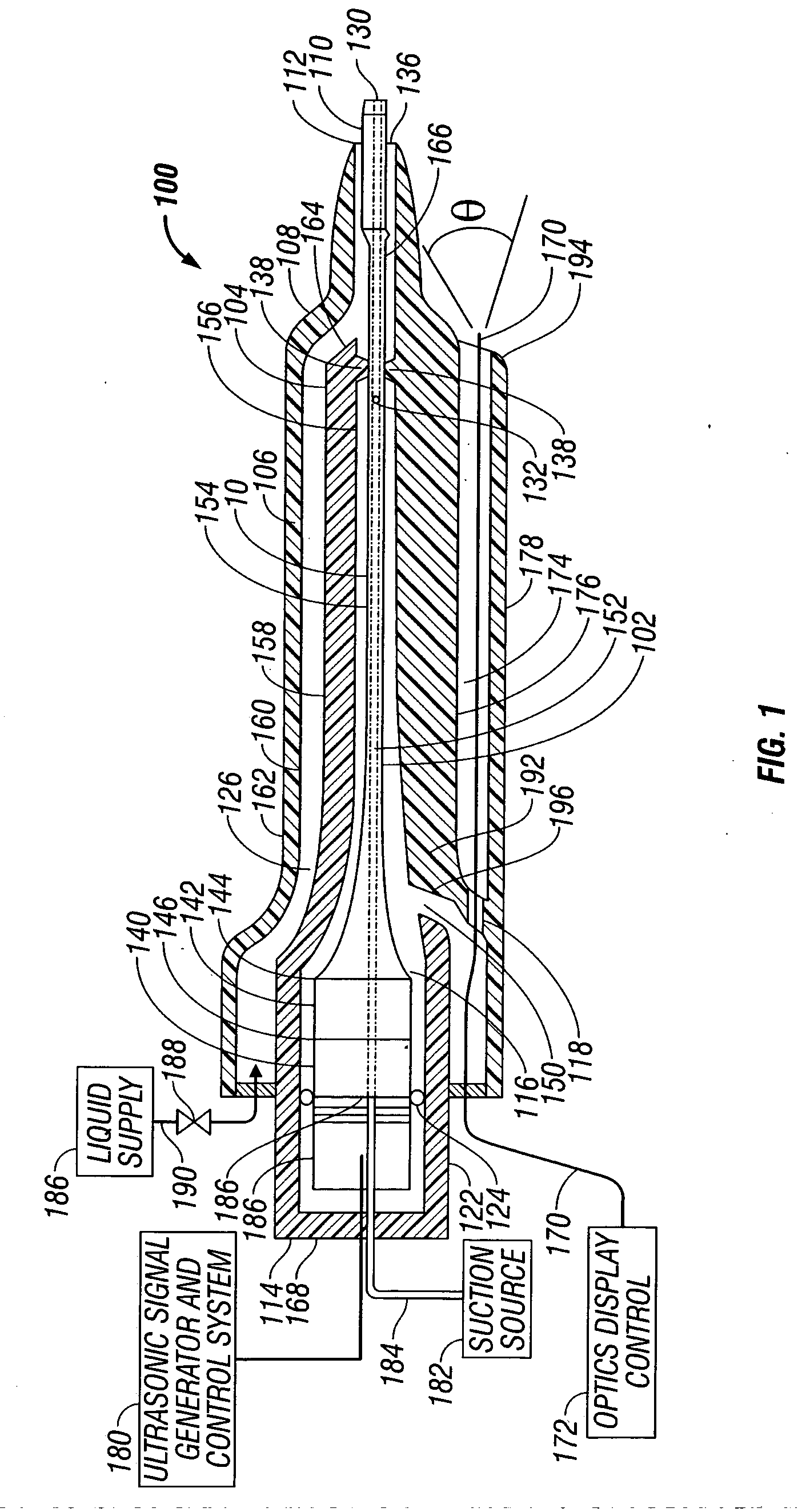
[0032]FIG. 1 illustrates one embodiment of the present disclosure of an ultrasonic horn assembly 100 which is adapted for use in an ultrasonic surgical system having an ultrasonic resonator and irrigation and aspiration channels. An example of such an ultrasonic surgical system is disclosed in commonly owned WIPO International Publication Number WO 2004 / 026150 A2 by Garrison et al. and assigned to Sherwood Services AG, a division of Tyco Healthcare Group LP, the entire contents of which are incorporated herein b...


PUM


Abstract

An ultrasonic horn assembly is configured so that irrigating fluid can be supplied only to a vibrating tip portion of the ultrasonic horn and so that suction aspiration can occur through a portion of the ultrasonic horn not in contact with the irrigating fluid. Controllers supplying irrigation fluid during a surgical procedure and controlling suction aspiration via monitoring of fluid level in the patient cavity are operatively coupled one to another to coordinate control of the fluid level in the patient cavity. Circuitry controlling power, frequency and amplitude of the tip of the ultrasonic horn occurring as a result of operation of a source of ultrasonic signal generating power controls either or both the supply of irrigation fluid and the suction aspiration so as to minimize damping of vibration of the tip of the ultrasonic horn. An optical viewing element is provided to view the tip of the ultrasonic horn.

Description

BACKGROUND [0001] 1. Technical Field [0002] This disclosure relates to surgical systems and, more particularly, to ultrasonic horns for fragmenting tissue in fluid filled cavities during a surgical procedure. [0003] 2. Background of Related Art [0004] It is known in the art of applying ultrasonic horns for fragmenting tissue in fluid filled cavities during a surgical procedure that energy is absorbed or dispersed from ultrasonic tips by fluid along the tip length. If fluid fills a flue around an ultrasonic tip or is aspirated without air inside of the tip, the energy loss renders the tip inoperative. Such conditions are most severe when an ultrasonic tip is used in environments such as a ventricle of the brain. [0005] What is needed is a method of irrigating tissue which isolates an ultrasonic tip from irrigation fluid, and provides an air path so that the condition rendering the tip as inoperative is mitigated or completely eliminated, even in environments such as a ventricle of th...

Claims


Application Information

Patent Timeline
IPC IPC(8): A61M1/00A61B17/22
CPCA61B17/320068A61B2019/5231A61B2017/320084A61B2090/373A61B2017/32007
Inventor SARTOR, JOE D.
Owner INTEGRA LIFESCI IRELAND
Learn More