Systems and methods for active vibration damping

a technology of active vibration and damping, applied in the field of active vibration damping systems, can solve the problems of shifting up the resonance frequency of the system, affecting the performance of the system, and requiring a relatively high level of damping, so as to minimize the vibration experienced and minimize the effect of feedback instability of the system

Inactive Publication Date: 2010-06-01
TECHN MFG
View PDF21 Cites 48 Cited by
  • Summary
  • Abstract
  • Description
  • Claims
  • Application Information

AI Technical Summary

Benefits of technology

[0008]The present invention provides an active vibration damping system that decouples static and dynamic forces generated by a payload, permits each of the two forces to be addressed by separate mechanisms, and improves vibration isolation by directing dynamic forces from the payload to an actively isolated point. The vibration damping system, in one embodiment, includes a supporting spring for addressing the static force from the payload mass, and an actively isolated damper positioned in parallel between the payload mass, such as an isolated platform, and a source of vibration, such as the floor, external casing, or a vibrating base platform, to damp the dynamic force from the payload mass. The actively isolated damper (“active damper”), in an embodiment, includes a small intermediate mass, distinct and elastically decoupled from the payload mass. The small intermediate mass may be at least one order of magnitude smaller than the range of masses that the system is designed to support or isolate, and may act as a support point for a dynamic load. The active damper also includes at least one actuator, such as a piezoelectric motor element, having a first surface coupled to the small intermediate mass and a second surface coupled to the vibrating base platform. The actuator may include a spring system designed to be at least one order of magnitude higher in stiffness than the supporting spring. The active damper further includes a passive isolator element, such as a passive fluid damper (“passive damper”), for coupling the isolated platform to the small intermediate mass. In one embodiment, a motion sensor may be coupled to the small intermediate mass, so as to generate a feedback signal to the actuator as a function of the movement of the small intermediate mass. The motion sensor may be designed to be decoupled from the isolated platform.
[0010]A shear decoupler may be positioned between the actuator and the intermediate mass situated along the actively controlled “Z” axis, so as to limit the exertion of shear stresses on the actuator. A shear decoupler may also be positioned in the “X” and “Y” axes between the respective actuators and the intermediate mass to minimize cross axis vibration.
[0011]According to another embodiment of the invention, additional compensation circuits can be employed by the compensation module to process signals sent from a sensor mounted on the payload mass. These signals, which may be representative of payload motions, can be combined with the signals from the motion sensor on the intermediate mass to further compensate for payload vibration.
[0013]The present invention provides, among other things, a practical active vibration damping system based on an active isolation damper and a supporting spring, both positioned between the payload mass and the base platform. The utilization of an active isolation damper having an intermediate mass with resonance frequency above the active bandwidth, along with a passive damper for decoupling the payload resonances from the intermediate mass as well as providing passive isolation outside of the active isolation frequency range, and an actuator to actively compensate floor vibration and create stiffness relatively higher than the stiffness of the supporting spring can minimize vibration experienced by the payload mass from environmental sources. In addition, the utilization of motion sensors can provide to the actuators, among other things, feedback signals based on motion signals from the various components to further minimize feedback instability to the system.

Problems solved by technology

Many currently available vibration isolation applications that are based upon “soft springs” also require relatively high level of damping.
Unfortunately, acceptable levels of damping can be very limited in most of the available systems.
One limiting factor can be attributed to the stiffness increase of the combined damper-spring system, which can result in shifting up the resonance frequency of the system, and in decreasing of the gain / frequency function, i.e., the “roll off” slope above the resonance frequency.
As a result, there tends to be a significant loss in vibration isolation gain beyond the resonance frequency.
However, since these dampers are usually coupled to the vibrating base platform, for frequencies above resonance frequencies, these dampers can reduce vibration isolation gains by approximately 20 dB per decade.
However, active dampers also have very limited active bandwidth gain.
In particular, the coupling of payload resonances with sensed outputs can compromise stability margins.
This limitation may be due to the servo loop stability that can be limited by the required attachment of vibration sensors to the isolated platform sensing its multiple resonances.
Such an approach requires the use of a very powerful actuator or multiple actuators, both of which can be expensive and bulky.
Moreover, finding a compromise between the damping level and vibration isolation gain can be a difficult engineering task.

Method used


Image

  • Systems and methods for active vibration damping
  • Systems and methods for active vibration damping
  • Systems and methods for active vibration damping

Examples


Embodiment Construction

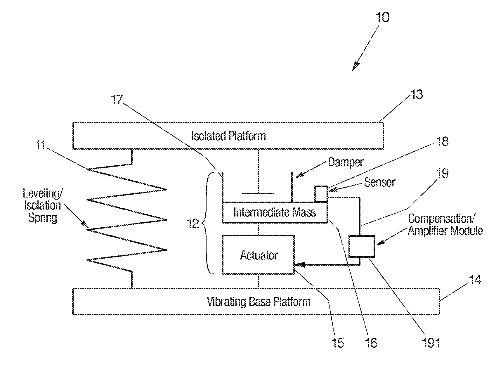
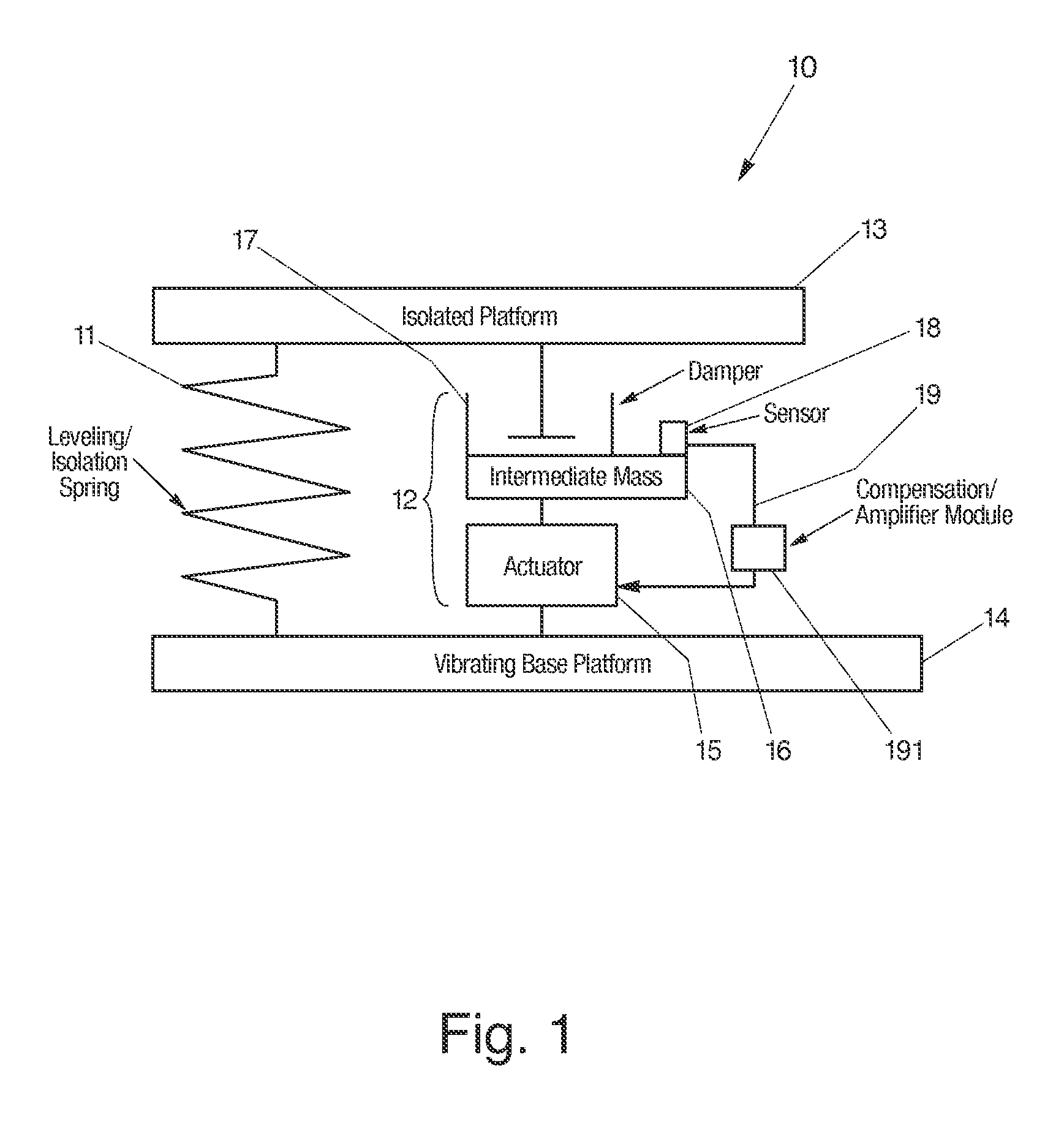
[0019]Supported payload typically generates static and dynamic forces, both of which must be addressed when compensating or minimizing the vibration caused by payload movement. To address both of these forces, the present invention provides a vibration damping system that decouples static and dynamic forces generated by a supported payload and permits each of the two forces to be addressed by separate mechanisms.

[0020]In FIG. 1, the present invention provides an active vibration damping system 10 that can resist or minimize supported payload movement due to payload-induced forces through the use of a supporting spring 11 for addressing static forces, and an independent actively isolated damper 12 (“active damper”) positioned in parallel to and spaced relation from the spring 11 for addressing dynamic forces. Both the spring 11 and active damper 12 may be positioned between a payload mass, such as that on or including an isolated platform 13, and a source of vibration, such as the fl...


PUM


Abstract

An active vibration damping system having a supporting spring for addressing a static force from a payload, and an independent actively isolated damper positioned in parallel between a payload and a source of vibration for damping dynamic force from the payload to an actively isolated point. The actively isolated damper includes a small intermediate mass, distinct and decoupled from the payload mass, and a passive isolator element for dynamic coupling of the isolated platform to the small intermediate mass. The small intermediate mass provides a point to which dynamic forces from the payload may be dampened. The active damper also includes at least one actuator coupled at one surface to the small intermediate mass and coupled at a second surface to the vibrating base platform. A motion sensor may also be provided on the small intermediate mass so as to generate a feedback signal as a function of the movement of the small intermediate mass. The motion sensor together with a compensation / amplifier module and the actuator act as part of a feedback compensation loop for minimizing vibration.

Description

TECHNICAL FIELD[0001]The present invention relates generally to methods and systems for active vibration damping of supported payloads, and more particularly to vibration damping systems and methods which decouple static and dynamic forces generated by the supported payloads and damps dynamic forces to an actively isolated point.BACKGROUND ART[0002]The need in industry for vibration isolation is growing. For example, there is less and less tolerance for environmental vibration in ultraviolet steppers used in semiconductor manufacturing. As the manufacturing of semiconductors and other products becomes more and more precise, the need for suppressing environmental vibration becomes greater and greater.[0003]Many currently available vibration isolation applications that are based upon “soft springs” also require relatively high level of damping. Dampers are often used to reduce vibration amplification at the resonance frequency of the spring, and to minimize distortion generated on the...

Claims


Application Information

Patent Timeline
Patent Type & Authority Patents(United States)
IPC IPC(8): F16F7/10F16M13/00
CPCF16F15/027F16F7/1017B60G2202/25B60G2202/32B60G2800/162B60G2600/182
Inventor KRANER, EMIL
Owner TECHN MFG
Why Eureka
Try Eureka