wind turbine and a method for monitoring a wind turbine

a wind turbine and blade technology, applied in the direction of motors, engine control, engine fuction, etc., can solve the problems of limited stress cycles of strain gages, easy breakage of optical fibers, cumbersome and time-consuming, etc., to achieve convenient implementation, advantageously increase the reliability and/or efficiency of blade monitoring, the effect of improving the efficiency of the

Active Publication Date: 2011-11-24
VESTAS WIND SYST AS
View PDF3 Cites 60 Cited by
  • Summary
  • Abstract
  • Description
  • Claims
  • Application Information

AI Technical Summary

Benefits of technology

[0007]The first and second radial positions are measured from the center of the rotor. By providing two accelerometers at different radial positions, a reliable and tolerant blade monitoring may be obtained. By using more than one accelerometer and providing them at different positions the blade monitoring may be continued even in case one accelerometer is damaged.
[0024]The signal generated by the controller may be a control signal and the controller may be adapted to control the operation of the wind turbine in accordance with the control signal. The controlling may comprise pitching the blade. The controlling may also comprise braking of the wind turbine or yawing the wind turbine. As an illustrative example, if the bending of the blade increases (increased difference between the determined first and second acceleration values, or between an acceleration estimate and a determined acceleration value) this may be countered by controlling the wind turbine accordingly. This may prevent large blade bending and overloading of the blade and wind turbine. The signal generated by the controller may also be used for monitoring purposes, wherein the signal may be provided to a control station and presented as e.g. a graph on a display. An operator at the control station may then track the behaviour of the blade and react to any anomalies in the operation of the blade.

Problems solved by technology

However, strain gages suffer from limited stress cycles and since they need to be embedded in the blade structure replacement is cumbersome and time consuming.
However, optical fibers are prone to breakage and embedding fibers in the blade structure adds to the complexity and cost of blade manufacturing.

Method used


Image

  •  wind turbine and a method for monitoring a wind turbine
  •  wind turbine and a method for monitoring a wind turbine
  •  wind turbine and a method for monitoring a wind turbine

Examples


first embodiment

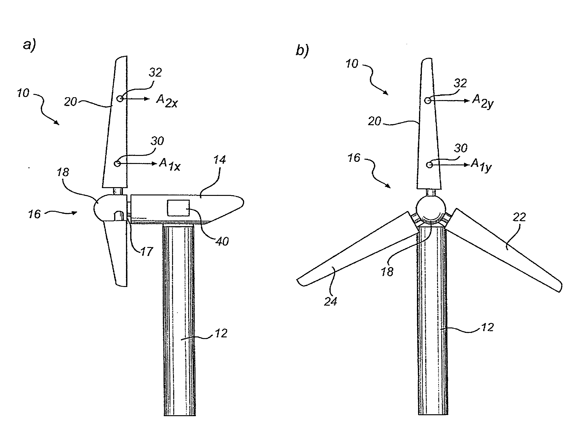
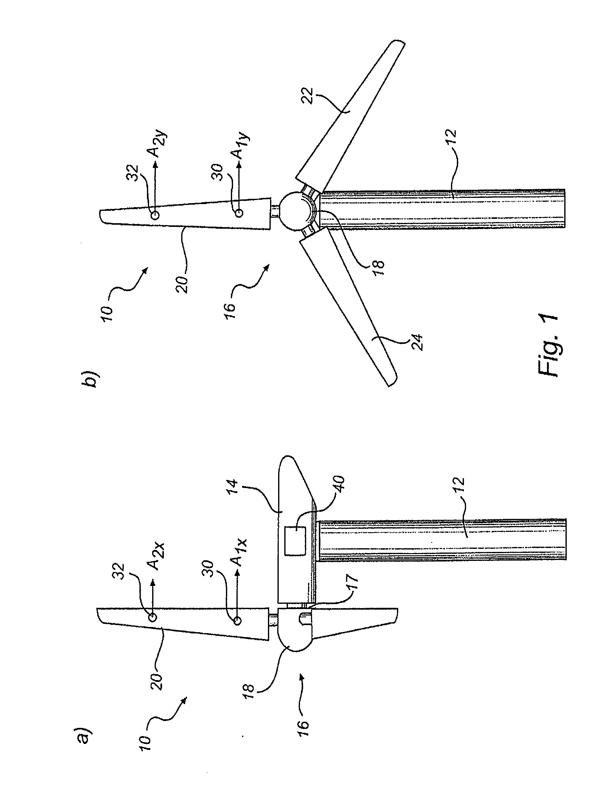
[0037]FIG. 1 illustrates a wind turbine 10 according to the present invention. The wind turbine 10 comprises a tower 12 and a nacelle 14 mounted on top of the tower 12. A rotor 16 comprising hub 18 and blades 20, 22, 24 are connected to a main shaft 17 of the nacelle 14. The blades 20, 22, 24 are connected to the hub 18 and are individually pitchable by a pitch mechanism (not shown) in the hub 18.

[0038]In operation the blades 20, 22, 24 of wind turbine 10 are subjected to various loads such as wind loads and loads resulting from the rotation of the blades 20, 22, 24. The loads acting on the blades 20, 22, 24 will deform and bend the blades 20, 22, 24. A blade 20, 22, 24 will bend essentially in two directions, orthogonal to a rotational plane of the blade (x-direction) and parallel to the tangential direction of the rotation of the blade (y-direction).

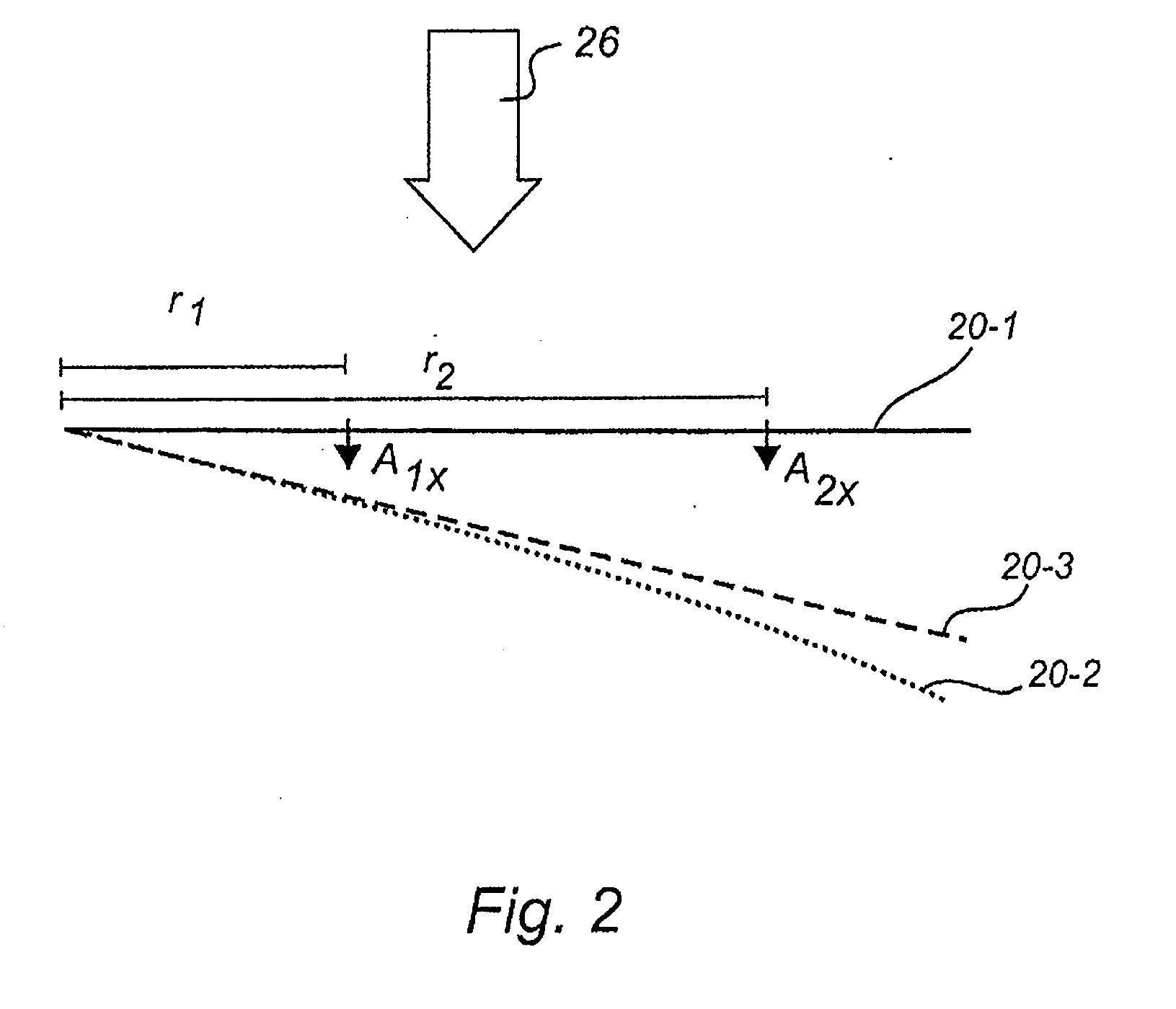
[0039]With reference to FIG. 2, a blade 20 is subjected to a load 26 due to wind, gravity or rotation etc. For clarity, the blade is ...

second embodiment

[0087]In accordance with a wind turbine 10, a blade 20 may be provided with three 2-axis accelerometers, see FIG. 5. Specifically, blade 20 is provided with first accelerometer 30, second accelerometer 32 and third accelerometer 34. The sensitive axes of the accelerometers are aligned as illustrated in FIG. 5. Consequently, the first, second and third accelerometer 30, 32, 34 measures acceleration in common directions.

[0088]The first accelerometer 30 is provided in a radially inner part of the blade 20, i.e. near or at the root of the blade 20. The second accelerometer 32 is provided in a mid-section of the blade 20. The third accelerometer 34 is provided in a radially outer part of the blade 20.

[0089]Other configurations are also possible, however the first, second and third accelerometer, or at least the acceleration sensitive part of the accelerometer in case a multi-part accelerometer is used, should be separated radially to such an extent that the blade may bend between each pa...


PUM


Abstract

According to the inventive concept, there is provided a wind turbine with at least one blade. The wind turbine comprises a first accelerometer mounted at a first radial position of the blade and being adapted to determine a first acceleration value, and a second accelerometer mounted at a second radial position of the blade different from the first radial position, and the accelerometer being adapted to determine a second acceleration value. The wind turbine further comprises a controller adapted to generate a signal based on said first and second acceleration values. There is also provided a method for monitoring a blade of a wind turbine.

Description

TECHNICAL FIELD [0001]The present invention generally relates to wind turbine technology. More specifically, the present invention relates to a wind turbine and a method for monitoring a blade of a wind turbine.BACKGROUND OF THE INVENTION[0002]In the prior art, wind turbine blades have been monitored using various sensors and technologies. For example strain gages have been embedded in the blade structure and used to estimate a local strain of the blade. However, strain gages suffer from limited stress cycles and since they need to be embedded in the blade structure replacement is cumbersome and time consuming.[0003]Furthermore, optical fibres have been embedded in the blade structure for estimating blade deformation from a change in transmission properties of the fibers as they are stretched during blade deformation. However, optical fibers are prone to breakage and embedding fibers in the blade structure adds to the complexity and cost of blade manufacturing.[0004]In the prior art...

Claims


Application Information

Patent Timeline
Patent Type & Authority Applications(United States)
IPC IPC(8): H02P9/04G06F15/00
CPCF03D1/06F03D7/0224F03D7/024F03D7/042Y02E10/723F05B2260/821F05B2270/807Y02E10/721F05B2260/80Y02E10/72
Inventor LI, XIAO QIANHVAS SANDVAD, INGEMANNNARASIMALU, SRIKANTH
Owner VESTAS WIND SYST AS
Why Eureka
Try Eureka