Supercharge Your Innovation With Domain-Expert AI Agents!

Chip structure

a technology of semiconductor chips and chips, applied in the direction of semiconductor devices, semiconductor/solid-state device details, electrical apparatus, etc., can solve the problem that the bump is unsuitable for being processed using a reflow process, and achieve the effect of maximizing the use of space over the passivation layer

Active Publication Date: 2011-12-01
QUALCOMM INC
View PDF2 Cites 9 Cited by
  • Summary
  • Abstract
  • Description
  • Claims
  • Application Information

AI Technical Summary

Benefits of technology

[0010]The objective of the invention is to provide a chip structure with a metal circuit layer formed over the passivation layer and functioning as signal transmission, power plane or ground plane, which makes the space employment over the passivation layer more efficiently.

Problems solved by technology

The bump is on the circuit layer, and the bump is unsuited for being processed using a reflow process.

Method used


Image

  • Chip structure
  • Chip structure
  • Chip structure

Examples


first embodiment

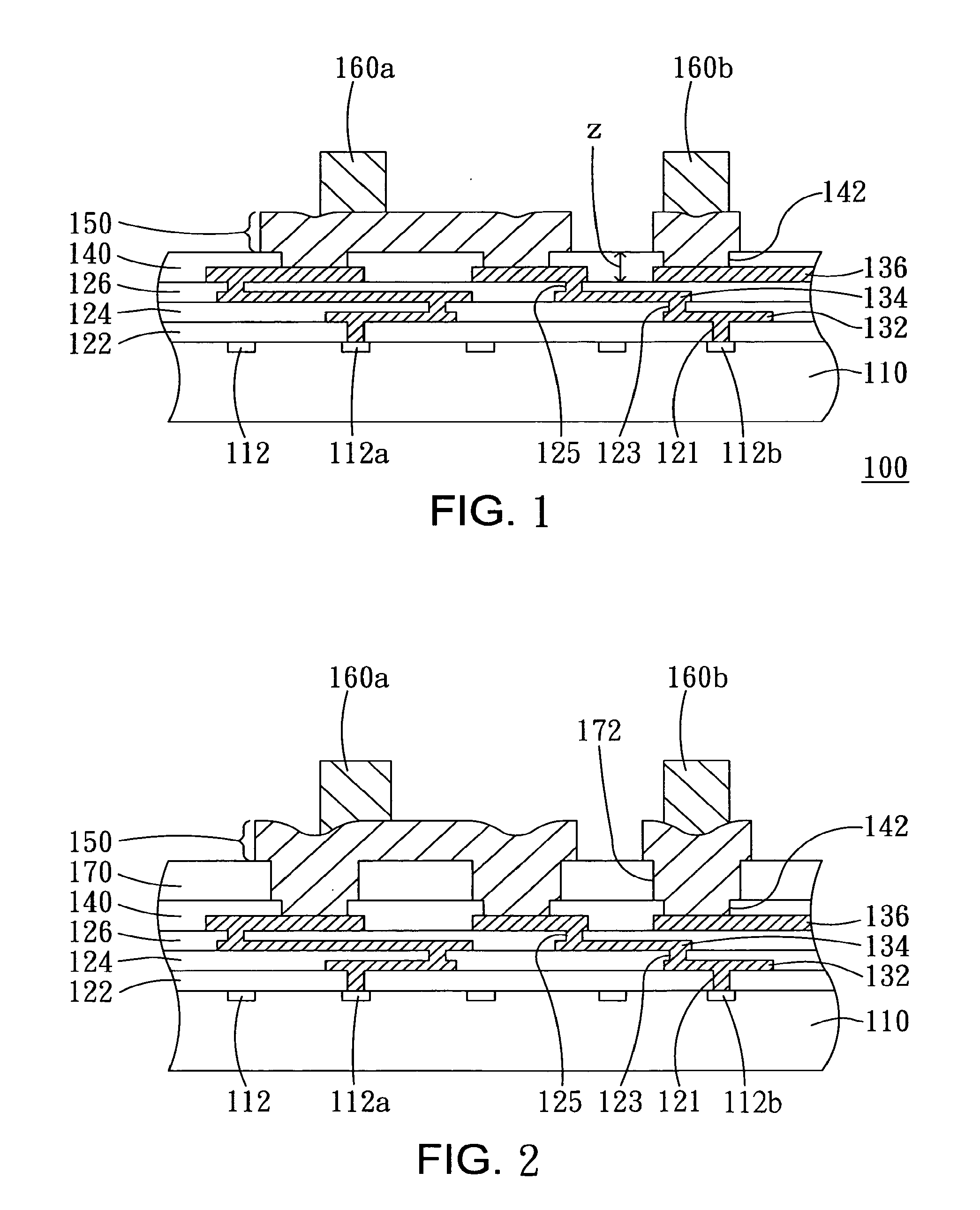
[0033]In the first embodiment, the metal circuit layer is placed over the passivation layer and the bump is placed over the metal circuit layer. This embodiment has several applications, as is illustrated in the following.

[0034]1. Application to Intra-Chip Signal Transmission

[0035]FIGS. 1-2 are schematic cross-sectional figure showing the chip structures or wafer structures according to a first embodiment of the present invention. The metal circuit layer 150, for example, is used for intra-chip signal transmission. The chip structure or wafer structure 100 comprises a semiconductor substrate 110, a plurality of thin film dielectric layers 122, 124 and 126, a plurality of thin film fine line metal layers 132, 134 and 136, and a passivation layer 140. The chip structure is obtained after sawing the wafer structure.

[0036]The semiconductor substrate 110 comprises a plurality of electronic devices 112 formed in or on the semiconductor substrate 110. The semiconductor substrate 110, for e...

second embodiment

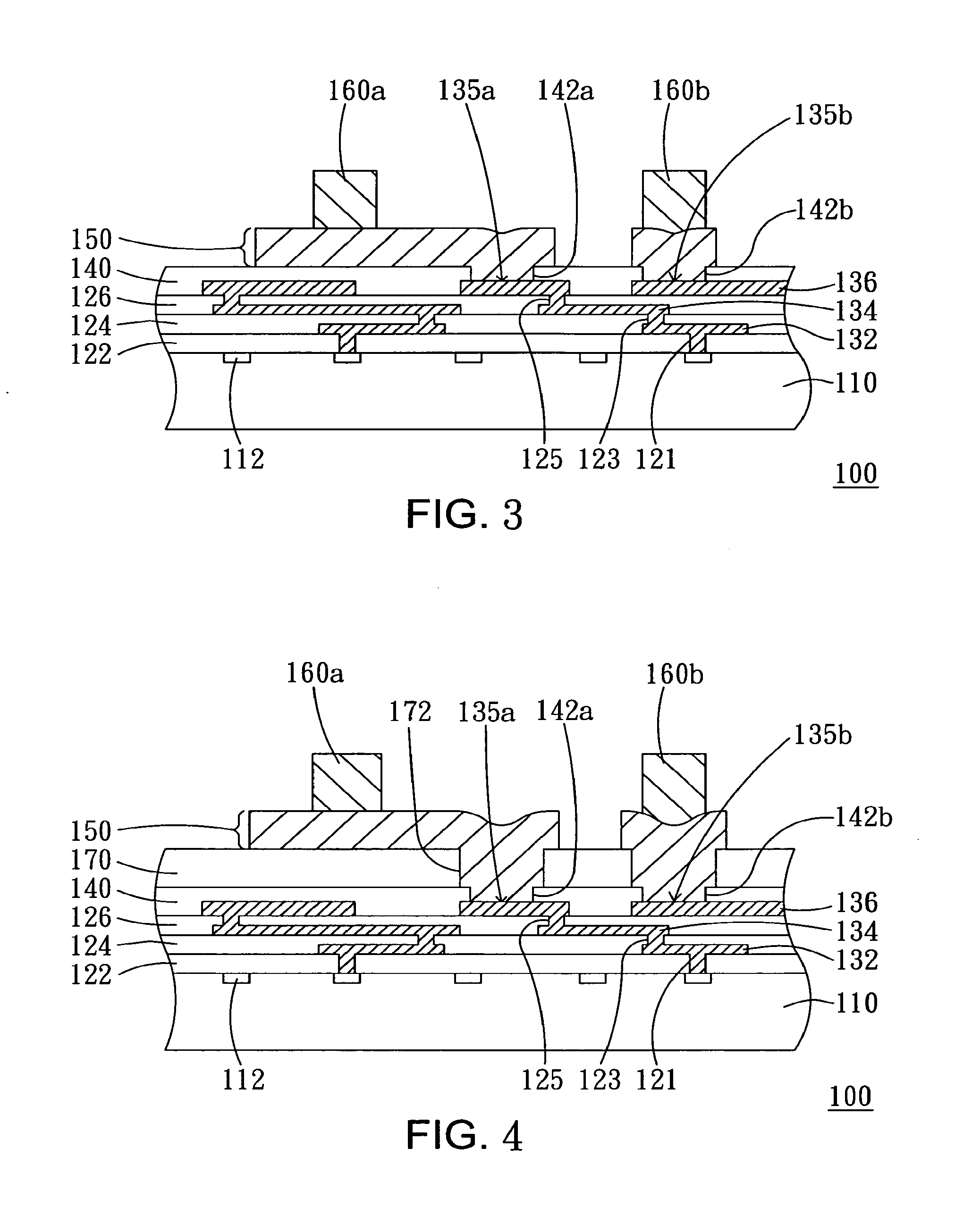
[0058]In the second embodiment, the metal circuit 250 is positioned over the passivation layer 140 and the bump 260 is positioned on the topmost thin film fine line metal layer 136. The components below the passivation layer 140 of the chip structure 200 in the second embodiment are similar to the above-mentioned in FIGS. 1-2.

[0059]This embodiment has several applications, as illustrated in the following.

[0060]1. Application to Intra-Chip Signal Transmission

[0061]FIGS. 11-23 are schematic cross-sectional figures showing the chip structures according to a second embodiment of the present invention. A circuit line at the left side of the metal circuit layer 250 is used for intra-chip signal transmission.

[0062]In FIGS. 11-23, a metal circuit layer 250 is formed over the passivation layer 140 and electrically connected to the thin film fine line metal layer 136 through openings 142 in the passivation layer 140. The metal circuit 250 connects multiple pads of the thin film fine line meta...


PUM


Abstract

A chip structure includes a semiconductor substrate, an interconnecting metallization structure, a passivation layer, a circuit layer and a bump. The interconnecting metallization structure is over the semiconductor substrate. The passivation layer is over the interconnecting metallization structure. The circuit layer is over the passivation layer. The bump is on the circuit layer, and the bump is unsuited for being processed using a reflow process.

Description

[0001]This application claims priority to U.S. Provisional Patent Application Ser. No. 60 / 586,840, filed on Jul. 9, 2004, which is herein incorporated by reference in its entirety.RELATED PATENT APPLICATION[0002]This application is related to Ser. No. ______ (MEGIC Docket No. MEG04-018), filed on Jul. 11, 2005, assigned to a common assignee, which is herein incorporated by reference in its entirety.BACKGROUND OF THE INVENTION[0003]1. Field of the Invention[0004]This invention relates to a semiconductor chip. More particularly, this invention relates to a semiconductor chip with metal circuit layers and bumps.[0005]2. Description of the Related Art[0006]Due to the advances that have been made in the information technology industry, it is no longer difficult to get quickly the information faraway. To achieve this goal, information technology companies with great competition produce more efficient products. With the evolution of the information industry, the latest generation of IC chi...

Claims


Application Information

Patent Timeline
Patent Type & Authority Applications(United States)
IPC IPC(8): H01L23/498
CPCH01L23/3114H01L23/525H01L24/13H01L24/10H01L2224/13099H01L2924/01005H01L2924/01011H01L2924/01013H01L2924/01015H01L2924/01022H01L2924/01029H01L2924/01046H01L2924/01073H01L2924/01074H01L2924/01078H01L2924/01079H01L2924/01082H01L2924/01322H01L2924/04941H01L2924/04953H01L2924/10329H01L2924/14H01L2924/19041H01L2924/19043H01L2924/01024H01L2924/01033H01L2924/01045H01L2924/01047H01L2924/014H01L2924/00H01L24/05H01L2224/023H01L2224/05001H01L2224/05022H01L2224/051H01L2224/05548H01L2224/05572H01L2224/056H01L2224/13H01L2224/13023H01L2224/13028H01L2924/15788H01L2924/00014H01L2924/0001H01L2224/05568
Inventor LIN, MOU-SHIUNGCHOU, CHIU-MING
Owner QUALCOMM INC
Features
  • R&D
  • Intellectual Property
  • Life Sciences
  • Materials
  • Tech Scout
  • Unparalleled Data Quality
  • Higher Quality Content
  • 60% Fewer Hallucinations
Learn More