Distributed configuration management for virtual cluster switching
What is Al technical title?
Al technical title is built by PatSnap Al team. It summarizes the technical point description of the patent document.
a virtual cluster and configuration management technology, applied in the field of network design, can solve the problems so as to achieve the effect of reducing the cost of switching
Active Publication Date: 2011-12-01
AVAGO TECH INT SALES PTE LTD
View PDF14 Cites 81 Cited by
Summary
Abstract
Description
Claims
Application Information
AI Technical Summary
This helps you quickly interpret patents by identifying the three key elements:
Problems solved by technology
Method used
Benefits of technology
[0016]On embodiment of the present invention provide a switch which maintains a set of configuration information for a virtual cluster switch. The virtual cluster switch includes a number of member switches. During operation, the switch receives an update to the set of configuration information, and confirms with another switch that the update is valid with respect to the set of configuration information maintained at the other switch. Based on the confirmation, the switch propagates the update to the member switches, thereby allowing the member switches to update their respective set of configuration information.
Problems solved by technology
However, the size of a switch cannot grow infinitely.
It is limited by physical space, power consumption, and design complexity, to name a few factors.
More importantly, because an overly large system often does not provide economy of scale due to its complexity, simply increasing the size and throughput of a switch may prove economically unviable due to the increased per-port cost.
However, switch stacking requires careful configuration of the ports and inter-switch links.
The amount of required manual configuration becomes prohibitively complex and tedious when the stack reaches a certain size, which precludes switch stacking from being a practical option in building a large-scale switching system.
Furthermore, a system based on stacked switches often has topology limitations which restrict the scalability of the system due to fabric bandwidth considerations.
Method used
Image
Click on the blue label to locate the original text in one second.
Reading with bidirectional positioning of images and text.
Examples
Embodiment Construction
[0033]The following description is presented to enable any person skilled in the art to make and use the invention, and is provided in the context of a particular application and its requirements. Various modifications to the disclosed embodiments will be readily apparent to those skilled in the art, and the general principles defined herein may be applied to other embodiments and applications without departing from the spirit and scope of the present invention. Thus, the present invention is not limited to the embodiments shown, but is to be accorded the widest scope consistent with the claims.
Overview
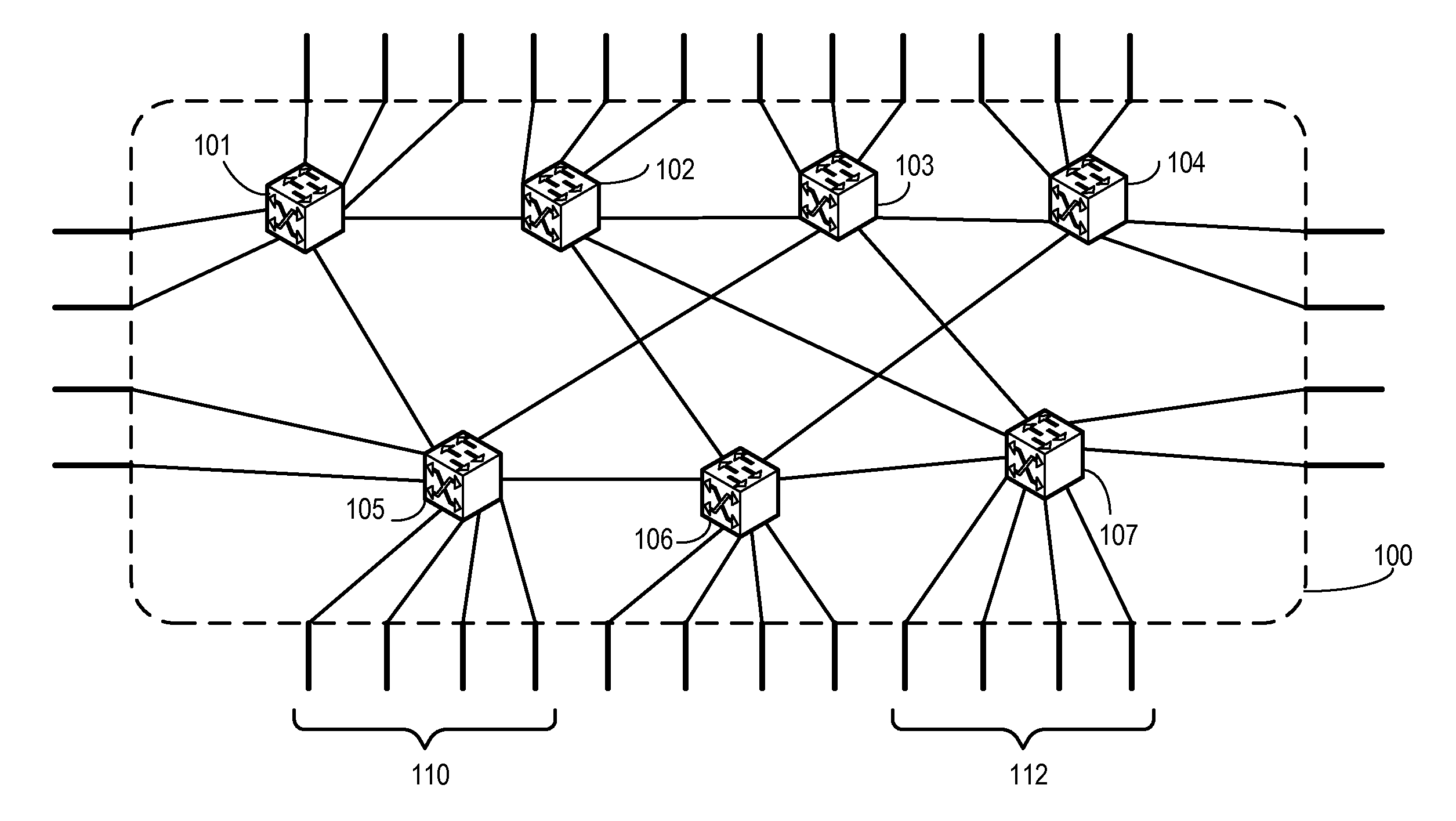
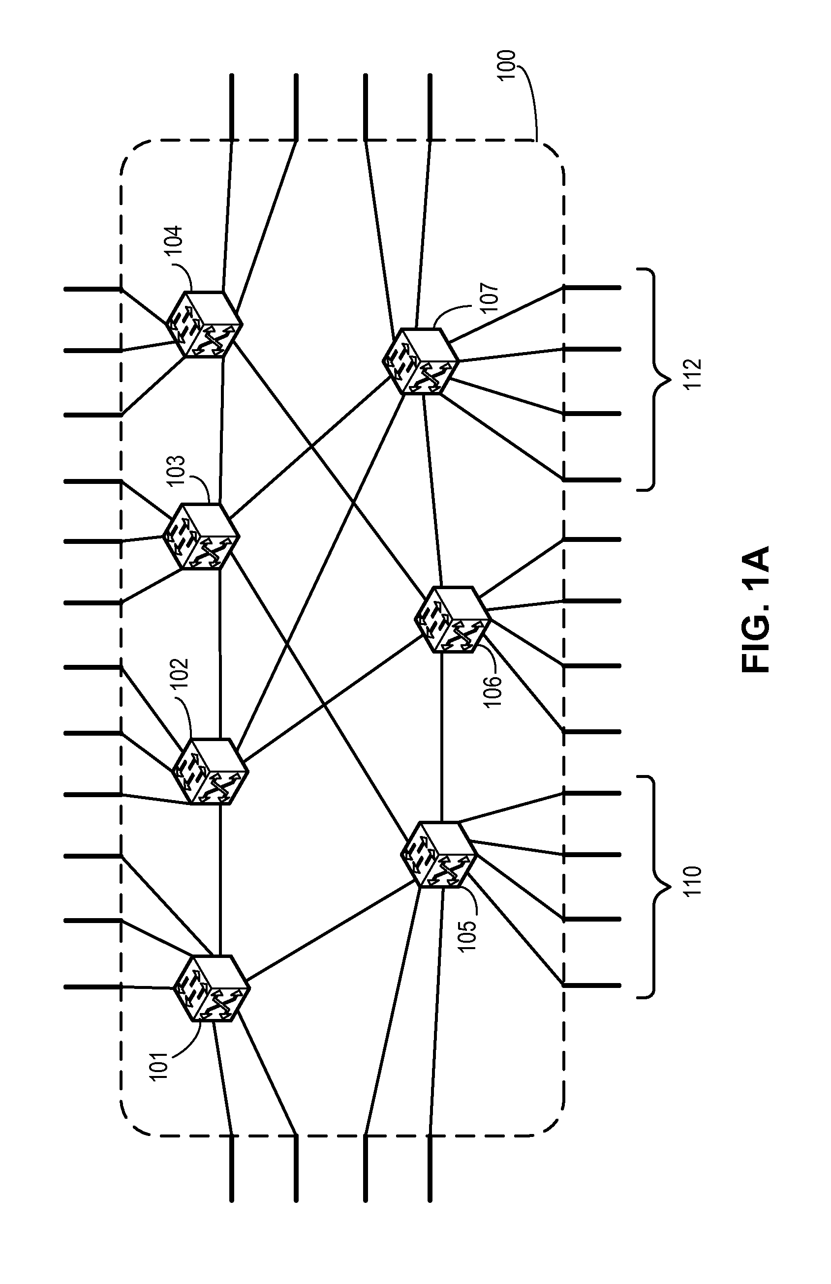
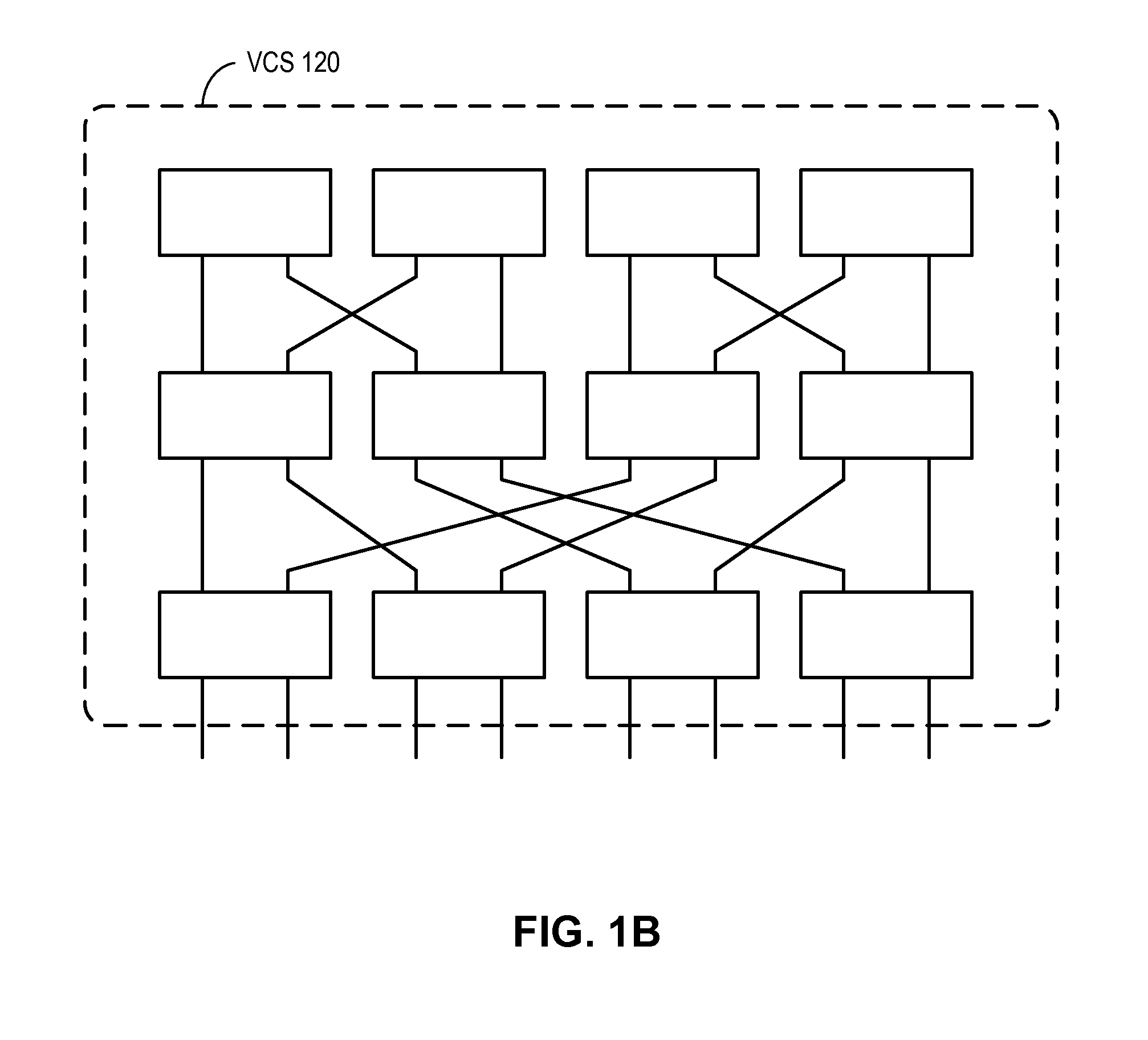
[0034]In embodiments of the present invention, the problem of building a versatile, cost-effective, and scalable switching system is solved by running a control plane with automatic configuration capabilities (such as the Fibre Channel control plane) over a conventional transport protocol, thereby allowing a number of switches to form a switch cluster that can be represented as a sing...
PUM
Abstract
One embodiment of the present invention provides a switch. The switch includes a port to couple to a second switch. The switch also includes a control mechanism configured to maintain a set of configuration information for a virtual cluster switch which includes a number of member switches. The set of configuration information includes global configuration information for the virtual cluster switch and switch-specific configuration information for one or more member switches. In addition, the set of configuration information is replicated and stored at each member switch.
Description
RELATED APPLICATIONS[0001]This application claims the benefit of U.S. Provisional Application No. 61 / 349,603, Attorney Docket Number BRCD-3011.0.1.US.PSP, entitled “Distributed Configuration Management For Virtual Cluster Switching,” by inventors Suresh Vobbilisetty, Shiv Haris, Phanidhar Koganti, and Vidyasagara R. Guntaka, filed 28 May 2010, and U.S. Provisional Application No. 61 / 380,818, Attorney Docket Number BRCD-3011.0.2.US.PSP, entitled “Distributed Configuration Management For Virtual Cluster Switching,” by inventors Suresh Vobbilisetty, Shiv Haris, Phanidhar Koganti, and Vidyasagara R. Guntaka, filed 8 Sep. 2010, the disclosure of which is incorporated by reference herein.[0002]The present disclosure is related to U.S. patent application Ser. No. 12 / 725,249, (attorney docket number BRCD-112-0439US), entitled “REDUNDANT HOST CONNECTION IN A ROUTED NETWORK,” by inventors Somesh Gupta, Anoop Ghanwani, Phanidhar Koganti, and Shunjia Yu, filed 16 Mar. 2010; and[0003]U.S. patent...
Claims
Application Information
Patent Timeline
Application Date:The date an application was filed.
Publication Date:The date a patent or application was officially published.
First Publication Date:The earliest publication date of a patent with the same application number.
Issue Date:Publication date of the patent grant document.
PCT Entry Date:The Entry date of PCT National Phase.
Estimated Expiry Date:The statutory expiry date of a patent right according to the Patent Law, and it is the longest term of protection that the patent right can achieve without the termination of the patent right due to other reasons(Term extension factor has been taken into account ).
Invalid Date:Actual expiry date is based on effective date or publication date of legal transaction data of invalid patent.
Patent Type & Authority Applications(United States)
IPC IPC(8): H04L12/56
CPCH04L49/70
Inventor VOBBILISETTY, SURESHHARIS, SHIVKOGANTI, PHANIDHARGUNTAKA, VIDYASAGARA R.