Eureka AIR delivers breakthrough ideas for toughest innovation challenges, trusted by R&D personnel around the world.

Seat back frame

Active Publication Date: 2011-12-08
HONDA MOTOR CO LTD +1
View PDF10 Cites 21 Cited by
  • Summary
  • Abstract
  • Description
  • Claims
  • Application Information

AI Technical Summary

Benefits of technology

[0010]Accordingly, the present invention aims to provide a seat back frame which can reduce the impact that a passenger receives from a seat when an impact is entered from a rear part of the vehicle. At the same time, the present invention aims to provide a seat back frame which can maintain the comfort level of a passenger who is sitting on a vehicle seat.
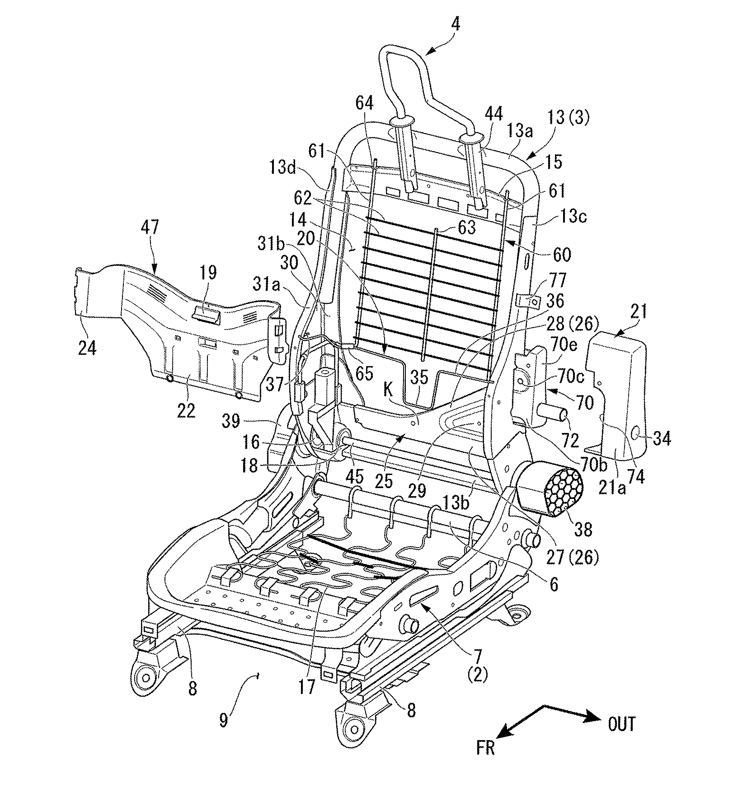
[0014]According to the present invention described in (1), a planar elastic body and a connection member is elastically strung at an upper opening. Therefore, when an impact load is entered from a rear part of the vehicle, the lumber vertebra and the dorsal vertebra may be sunk into the upper opening without restricting the movement of the lumber vertebra and the dorsal vertebra to a rear direction. Therefore, the head part and the neck part of the passenger can approach the head rest at an early stage. Thus, the neck part of the passenger may be protected.
[0015]Further, while the lumbar vertebra and the dorsal vertebra are sunk into the upper opening, the head part and the neck part are pushed towards the head rest. As a result, the efficiency with which the impact is absorbed is enhanced. Thus, it is possible to reduce the impact being applied to the head part and the neck part of the passenger.
[0016]In particular, a connection member is elastically strung between the planar elastic body and the supporting plate. As a result, when the passenger sits back towards the seat back (seat back frame) in a normal instance, the connection member and the planar elastic body elastically deforms along the back surface of the passenger in the upper opening. Therefore, the passenger no longer feels a concaved and convex terrain at an upper rim part of the supporting plate. Thus, any discomfort is dissolved when the passenger sits down on the vehicle seat. In this way, it is possible to maintain a good comfort level.
[0017]According to the invention described in (2), the connection member comprises a wire member. As a result, the manufacturing cost may be lowered. Further, the connection member may be set up easily according to the layout of the planar elastic body and the supporting plate. Therefore, it is possible to increase the efficiency of manufacturing.
[0018]According to the invention described in (3), the wire member may be easily fixed to the supporting plate. Therefore, it is possible to further increase the efficiency of manufacturing.

Problems solved by technology

However, according to the configuration disclosed in Patent Document 1, the comfort level of the passenger sitting on the seat in normal instances was not very good.
Therefore, there is a problem in that, when the passenger sits on the seat, the passenger may feel uncomfortable.

Method used


Image

  • Seat back frame
  • Seat back frame
  • Seat back frame

Examples


Embodiment Construction

[0031]Hereinafter, an embodiment of the present invention is described based on the attached diagrams.

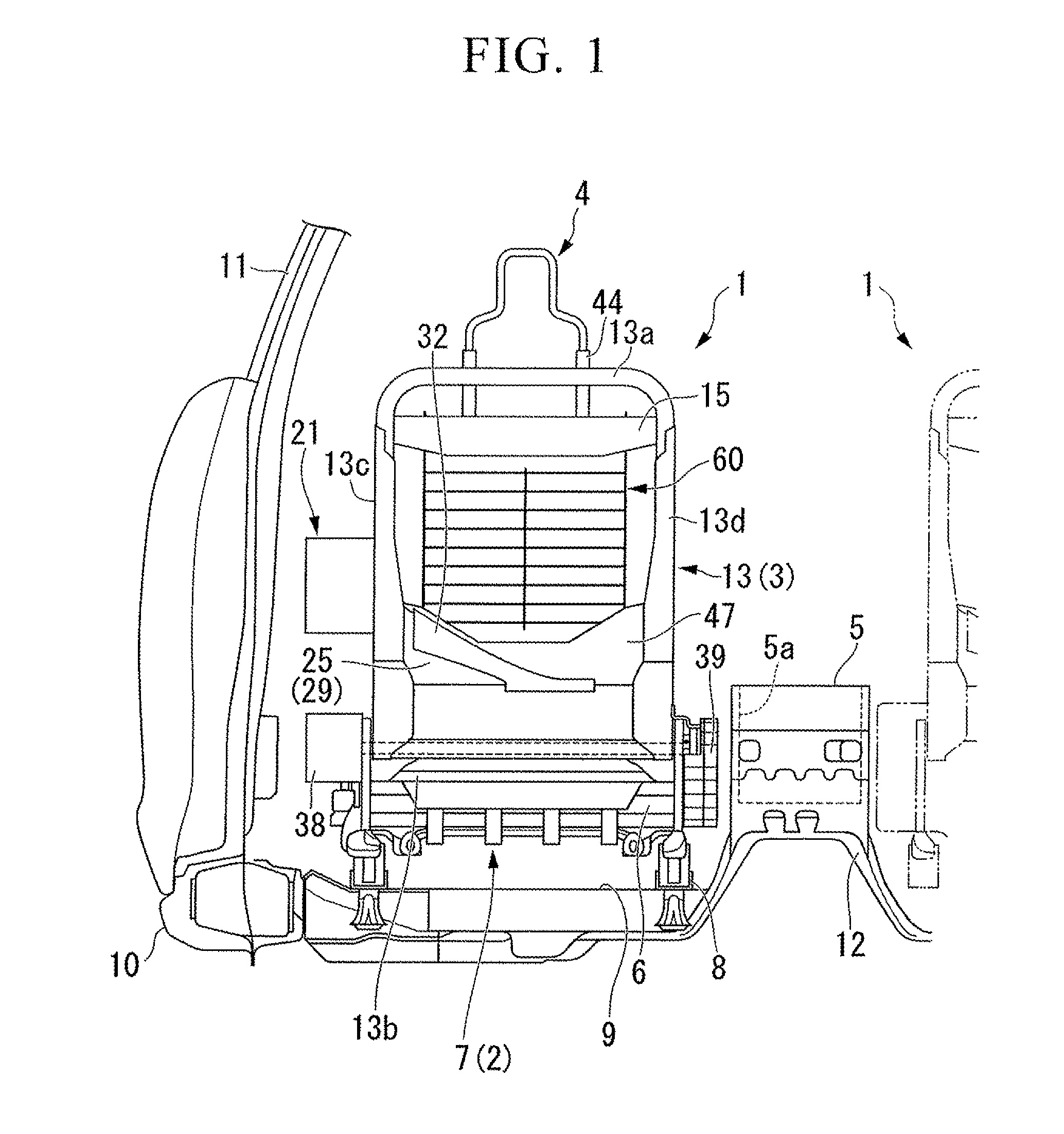
[0032]FIG. 1 is a diagram showing a rear side of a front seat at a left side of a vehicle chamber. According to the diagram, the arrow FR indicates a frontal direction of the vehicle. The arrow OUT indicates an outer side of the vehicle in a vehicle width direction.

[0033]As shown in FIG. 1, a floor tunnel 12 is formed on a vehicle body floor 9 at a central portion of a vehicle width direction. The floor tunnel is shaped so as to be concaved upward along a front-rear direction of the vehicle body. At both sides of the floor tunnel 12, a pair of left and right from seats 1, 1, are positioned separately from one another.

[0034]At an outer side of the left and right seats 1, 1 in the vehicle chamber, a side sill 10 is provided in a front-rear direction of the vehicle body. The side sill 10 is configured to be a closed structure in cross sectional view. The side sill 10 is grafted to a ri...


PUM


Abstract

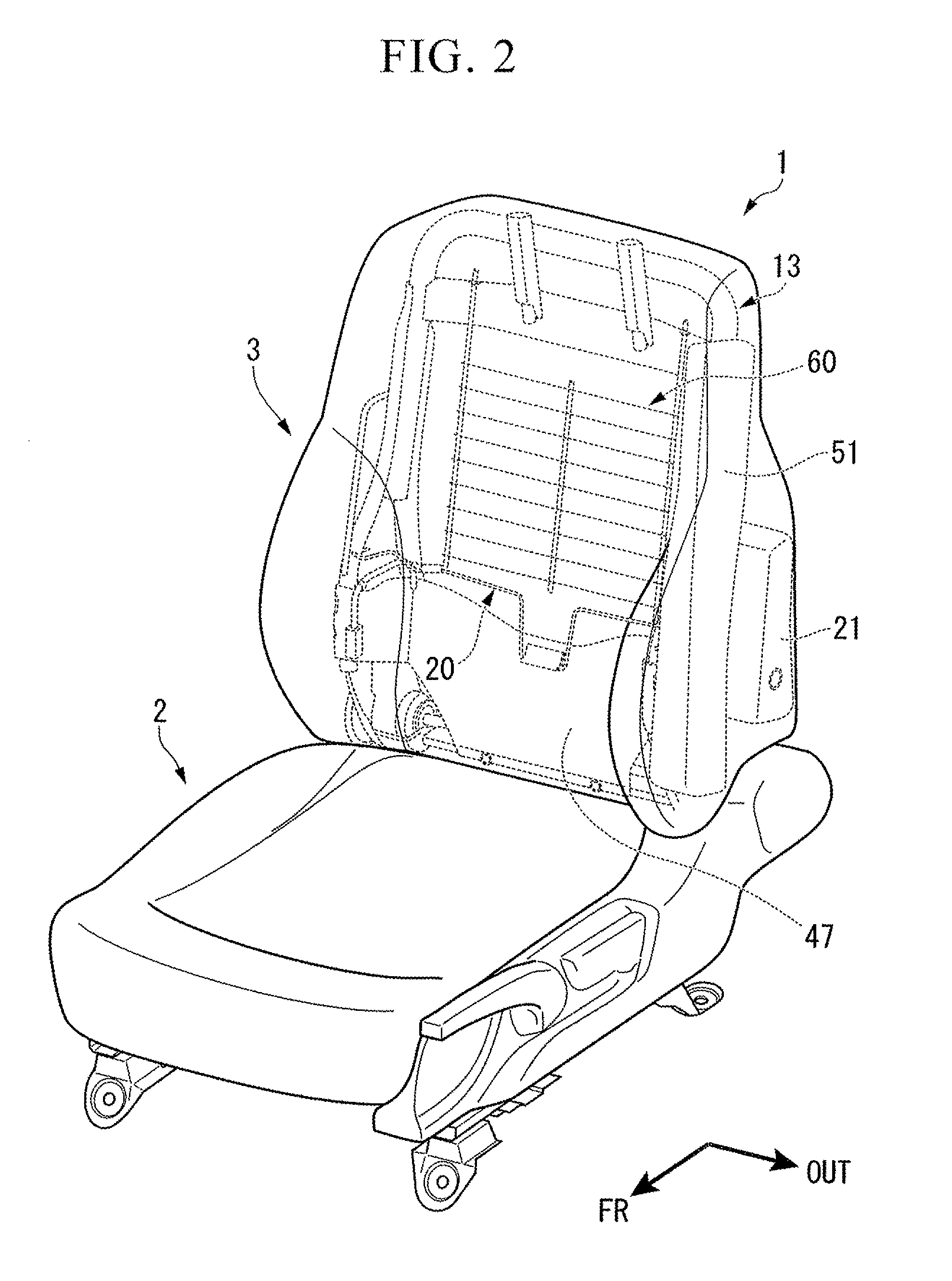
A seat back frame for a seat of a vehicle includes: a pair of side frames placed at a left side and a right side in a width direction of a seat; a head rest supporting frame supporting a head rest; a supporting plate, a both ends of the supporting plate being connected to a lower portion of each of the side frames; an upper opening provided above the supporting plate, the upper opening being opened in a front-rear direction; a planar elastic body provided across the upper opening; and a connection member elastically connecting a lower portion of the planar elastic body and an upper portion of the supporting plate.

Description

BACKGROUND OF THE INVENTION[0001]The present application claims priority on Japanese Patent Application No. 2010-129224, filed Jun. 4, 2010, the content of which is incorporated herein by reference.[0002]1. Field of the Invention[0003]The present invention relates to a seat back frame for a vehicle. The seat back frame comprises a feature such that a movement of an upper body of a passenger is controlled when an impact is entered from a rear part of the vehicle.[0004]2. Description of the Related Art[0005]A seat back frame for a vehicle is suggested in Japanese Unexamined Patent[0006]Application, First Publication No. H10-181400 (hereinafter referred to as Patent Document 1). This seat back frame is provided at a position corresponding to an upper portion of the pelvis of a passenger seated on a seat. In order to quickly reduce the space between the head part of the passenger and the head rest when an impact load is entered from a rear part of the vehicle, the seat back frame compri...

Claims


Application Information

Patent Timeline
IPC IPC(8): B60N2/68B60N2/48
CPCB60N2/4228B60N2/42745B60N2/66B60N2/72B60N2/686B60N2/7011B60N2/682B60N2/667
Inventor YAMAKI, JOGENNISHIDE, HARUTOMIOKA, YOSHITOMISAITO, KENICHIFURUTA, YOZOOKU, HISATOABE, HIROSHINISHIHARA, MUNETOSHI
Owner HONDA MOTOR CO LTD
Why Eureka
Eureka Blog
Learn More