Driving device

a technology of fastening elements and driving devices, which is applied in the direction of manufacturing tools, nailing tools, tapering tools, etc., can solve the problems of energy with which the fastening element is driven into the substrate has an upper limit, and the device cannot be used universally for all fastening elements and every substra

Inactive Publication Date: 2011-12-15
HILTI AG
View PDF30 Cites 11 Cited by
  • Summary
  • Abstract
  • Description
  • Claims
  • Application Information

AI Technical Summary

Problems solved by technology

In such devices, the energy with which the fastening element is driven into the substrate has an upper limit, so that the devices cannot be used universally for all fastening elements and every substrate.

Method used


Image

  • Driving device
  • Driving device
  • Driving device

Examples


Embodiment Construction

[0171]Below, embodiments of a device for driving a fastening element into a substrate will be explained in detail using examples with reference to the drawings. Shown are:

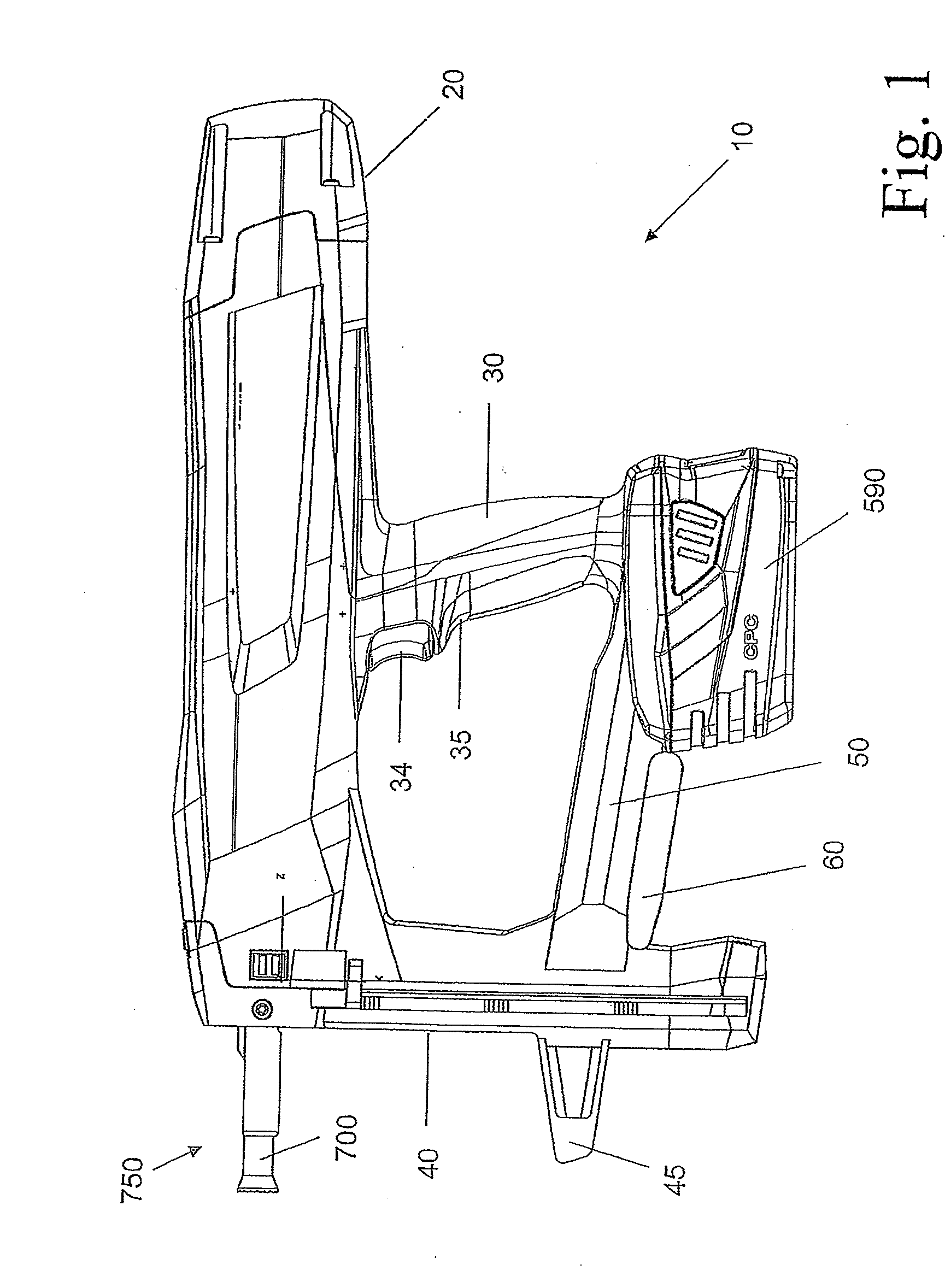
[0172]FIG. 1, a side view of a driving device;

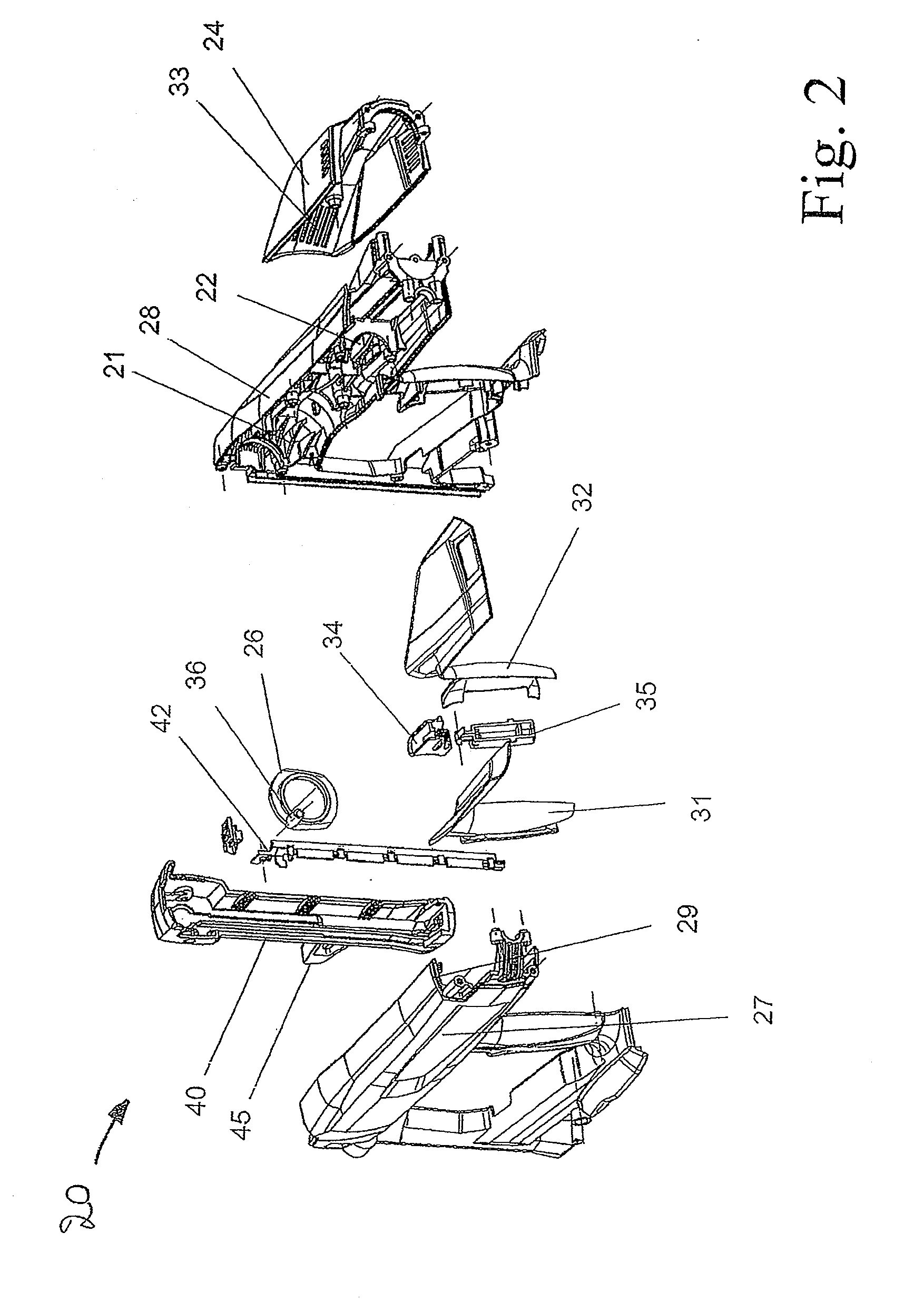
[0173]FIG. 2, an exploded view of a housing;

[0174]FIG. 3, an exploded view of a frame hook;

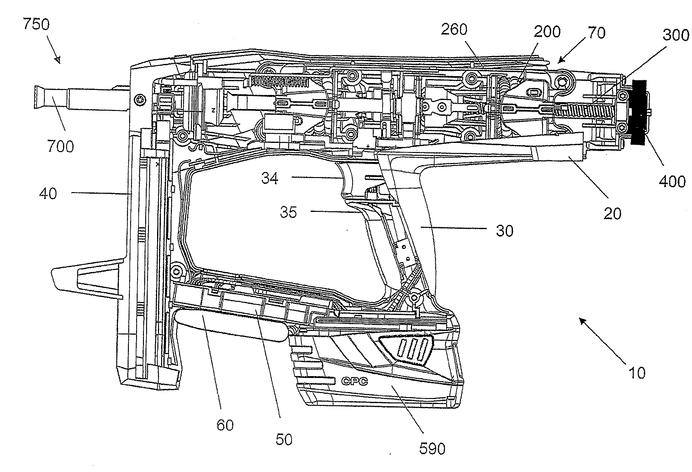
[0175]FIG. 4, a side view of a driving device with opened housing;

[0176]FIG. 5, a perspective view of an electrical-energy storage device;

[0177]FIG. 6, a perspective view of an electrical-energy storage device;

[0178]FIG. 7, a partial view of a driving device;

[0179]FIG. 8, a partial view of a driving device;

[0180]FIG. 9, a perspective view of a control mechanism with wiring;

[0181]FIG. 10, a longitudinal section of an electric motor;

[0182]FIG. 11, a partial view of a driving device;

[0183]FIG. 12a, a perspective view of a spindle drive;

[0184]FIG. 12b, a longitudinal section of a spindle drive;

[0185]FIG. 13, a perspective view of a tensioning device;

[0186]FIG. 14, a perspective view o...


PUM


Abstract

According to one aspect of the application, a device for driving a fastening element into a substrate has an energy-transfer element for transferring energy to the fastening element. The energy-transfer element can move preferably between a starting position and a setting position, wherein the energy-transfer element is located, before a driving-in procedure, in the starting position and, after the driving-in procedure, in the setting position.According to another aspect of the application, the device comprises a mechanical-energy storage device for storing mechanical energy. The energy-transfer element is then suitable preferably for transferring energy from the mechanical-energy storage device to the fastening element.

Description

FIELD OF THE TECHNOLOGY[0001]The application relates to a device for driving a fastening element into a substrate.PRIOR ART[0002]Such devices typically have a piston for transferring energy to the fastening element. The energy required for this purpose must be made available within a very short time, which is why, for example, in the case of so-called spring nailers, a spring is initially set in tension and outputs the tension energy onto the piston like an impulse during the driving-in procedure for this piston to accelerate onto the fastening element.[0003]In such devices, the energy with which the fastening element is driven into the substrate has an upper limit, so that the devices cannot be used universally for all fastening elements and every substrate. Therefore, it is desirable to make available driving devices that can transfer sufficient energy to a fastening element.PRESENTATION OF THE INVENTION[0004]According to one aspect of the application, a device for driving a faste...

Claims


Application Information

Patent Timeline
Patent Type & Authority Applications(United States)
IPC IPC(8): B25C1/06B25C1/00
CPCB25C1/06
Inventor FRANZ, KARLFIELITZ, HARALDSCHIESTL, ULRICH
Owner HILTI AG
Why Eureka
Try Eureka