Integrated ventilation unit

a ventilation unit and integrated technology, applied in space heating and ventilation control systems, lighting and heating apparatuses, heating types, etc., can solve the problems of non-primary design of high outside air, mechanically complex and inferior systems, non-integration of performance solutions, and inefficient energy consumption

Active Publication Date: 2011-12-22
THERMA STOR LLC
View PDF4 Cites 122 Cited by
  • Summary
  • Abstract
  • Description
  • Claims
  • Application Information

AI Technical Summary

Problems solved by technology

This solution is not primarily designed for high outside air ventilation applications.
As a result, this solution presents a mechanically complex and inferior system and one in which the performance solution is non-integrated and inefficient with regards to en

Method used


Image

  • Integrated ventilation unit
  • Integrated ventilation unit
  • Integrated ventilation unit

Examples


Embodiment Construction

[0009]The following detailed description refers to the accompanying drawings. The same reference numbers in different drawings may identify the same or similar elements. Also, the following detailed description does not limit the invention.

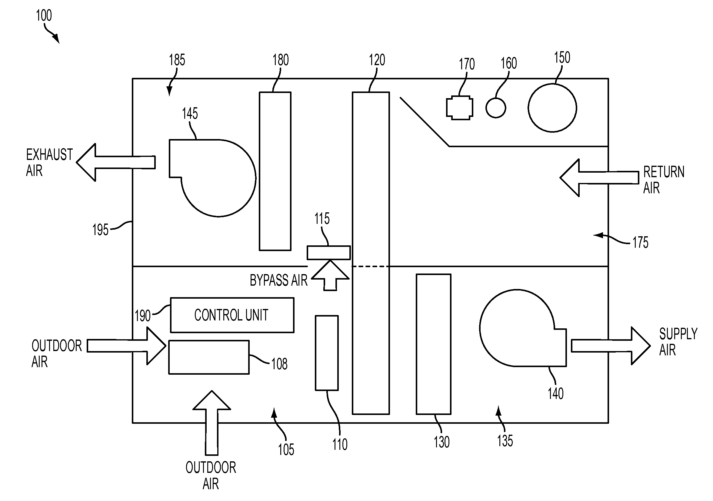
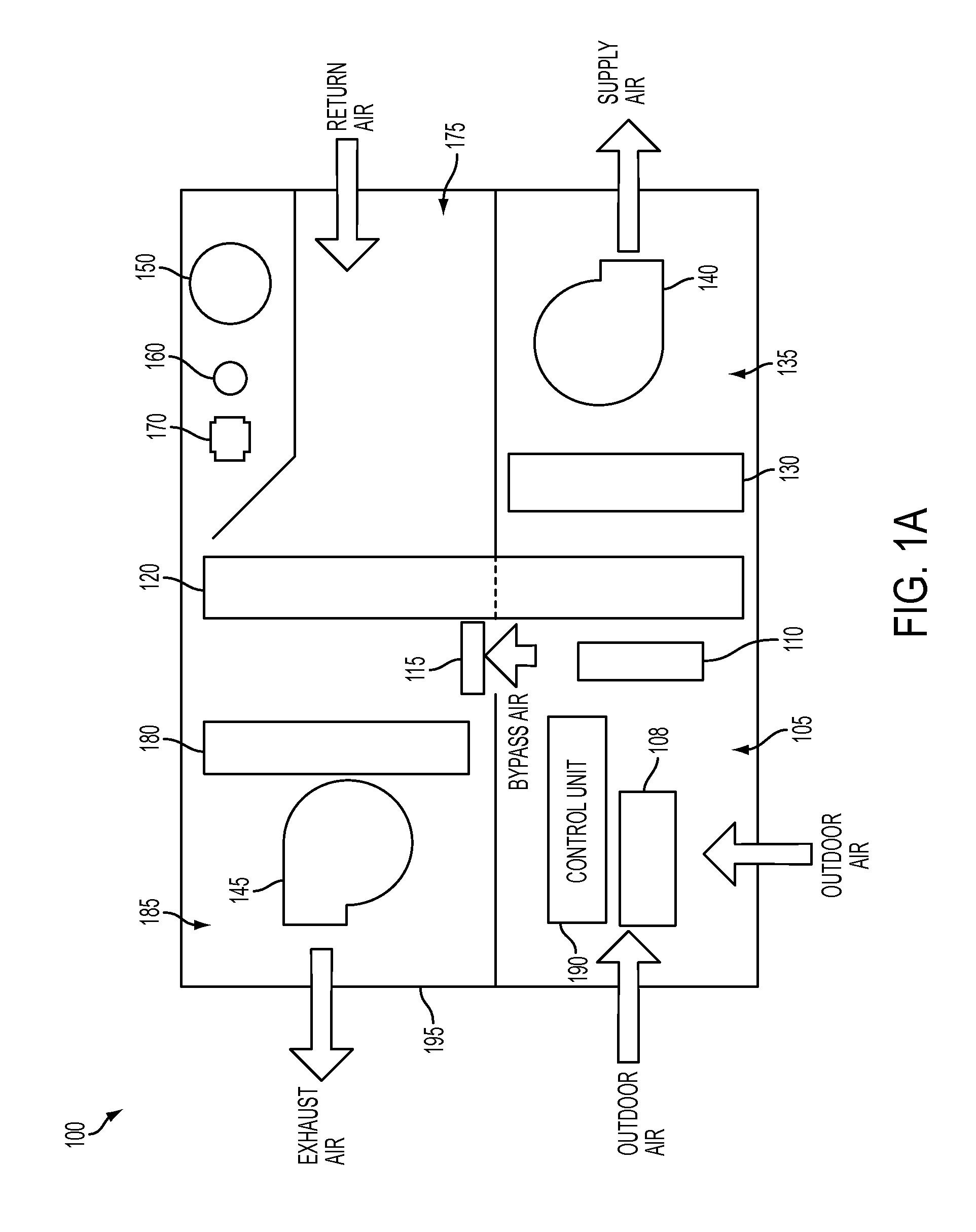
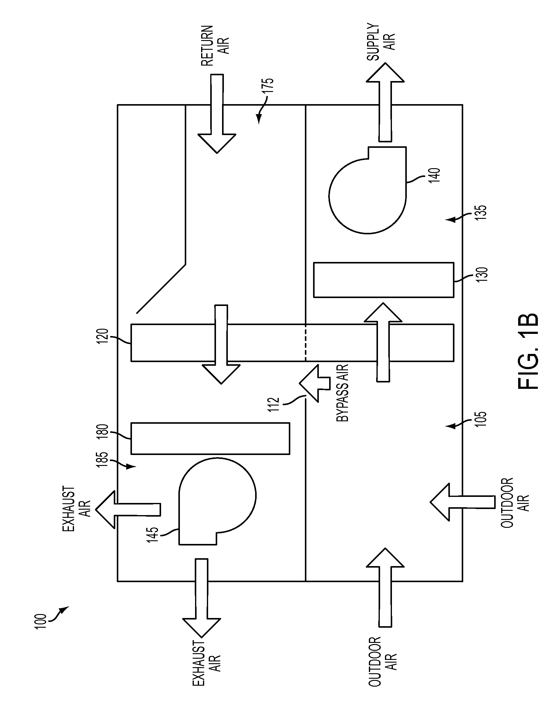
[0010]Embodiments described herein provide a device that exhausts a given amount of indoor air to the outdoors while delivering a near equal amount of outdoor air to an indoors space or other equipment for ventilation purposes. In an exemplary implementation, the device operates on two different air streams, a fresh air stream and a return / exhaust air stream. The device has a relatively compact design and is energy efficient to allow it to transfer energy between the exhaust air stream and the fresh air stream. The transferred energy “conditions” the fresh air such that it heats / cools the air to a desired leaving air temperature and may also remove excess humidity. For example, in the winter, the cold outdoor air is heated by the warmer indoor air...


PUM


Abstract

An integrated ventilation unit configured to provide ventilation and conditioned air to an indoor space may include a heat pump system, an energy recovery device and a control unit. The heat pump system may include a first coil located at a supply air side of the ventilation unit, a second coil located at an exhaust air side of the ventilation unit, and a compressor. The energy recovery device may be configured to transfer heat between a return air stream and a supply air stream and the control unit may be configured to control operation of the heat pump system and the energy recovery device.

Description

RELATED APPLCATION[0001]This application claims priority under 35 U.S.C. §119 based on U.S. Provisional Patent Application No. 61 / 355,200, filed Jun. 16, 2010, the disclosure of which is hereby incorporated herein by reference.BACKGROUND INFORMATION[0002]Industry standards for improved indoor air quality are requiring higher amounts of outside air for ventilation. These building standards are placing increased importance on achieving comfortable and healthy indoor living conditions with greatly reduced energy consumption. Conventional heat pump and energy recovery technologies typically exist as separate components that are used in space heating and air-conditioning systems. These conventional space conditioning units are sometimes applied to high dilution ventilation applications, either as separate or field combined components. This solution is not primarily designed for high outside air ventilation applications. As a result, this solution presents a mechanically complex and infer...

Claims


Application Information

Patent Timeline
IPC IPC(8): F25B49/00
CPCF24F12/001Y02B30/563F24F2203/104F24F2012/007F24F3/0442F24F3/1423F24F12/006F24F2203/1032F24F11/30F24F2110/10F24F2110/12F24F11/70F24D15/04F24F11/77F24F11/84F24F11/46F24F11/526F24F11/63F24F11/86F24F2140/00Y02B30/56F25B49/022Y02B30/12F24F11/62
Inventor PHANNAVONG, SENG K.HUGHES, CHRISTOPHER A.CLARK, THOMAS W.MCKISSACK, JOHN P.STREET, DAVID G.ROBERTS, TIMOTHY J.
Owner THERMA STOR LLC
Why Eureka
Try Eureka