Anti-Tracking Feature for Rock Bits

a technology of anti-tracking and rock bits, which is applied in the field of drill bits, can solve the problems of reducing the unit load of the cutting element, affecting the cutting effect, and affecting the cutting effect, and achieves the effect of reducing the tracking

Inactive Publication Date: 2011-12-29
BAKER HUGHES INC
View PDF5 Cites 3 Cited by
  • Summary
  • Abstract
  • Description
  • Claims
  • Application Information

AI Technical Summary

Benefits of technology

The cutter design removes the peak of the uncut bottom left by the other roller cones, significantly removing the depth of the pocket and allowing the other roller cones to continue to cut with their crests rather than with the sides of their active teeth or with their cones. Tracking is reduced regardless of the tooth count in the other rows or weight on bit. The invention may be used on any cutter row that shares a common bit diameter and not just the outermost row. Moreover, the invention may be used on a different roller cone or row, or more than one cutter row that shares a common bit diameter.

Problems solved by technology

These ridges are detrimental because they grow in height until they contact the supporting metal of the cone.
This lowers the unit load on the cutting elements and causes undesirable erosion and wear.
While workable, a wider pitch means fewer cutting elements and less durability.

Method used


Image

  • Anti-Tracking Feature for Rock Bits
  • Anti-Tracking Feature for Rock Bits
  • Anti-Tracking Feature for Rock Bits

Examples


Embodiment Construction

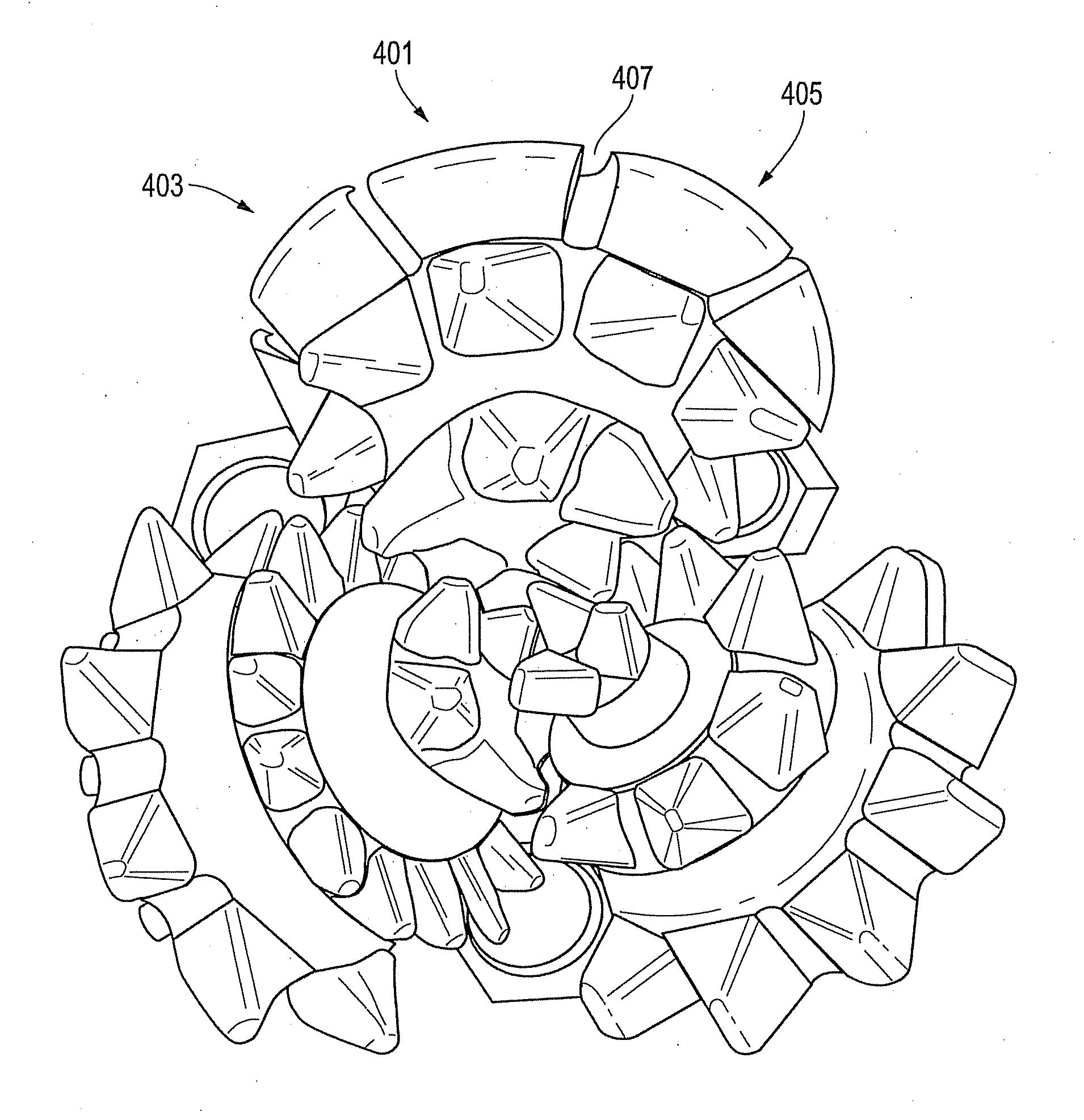
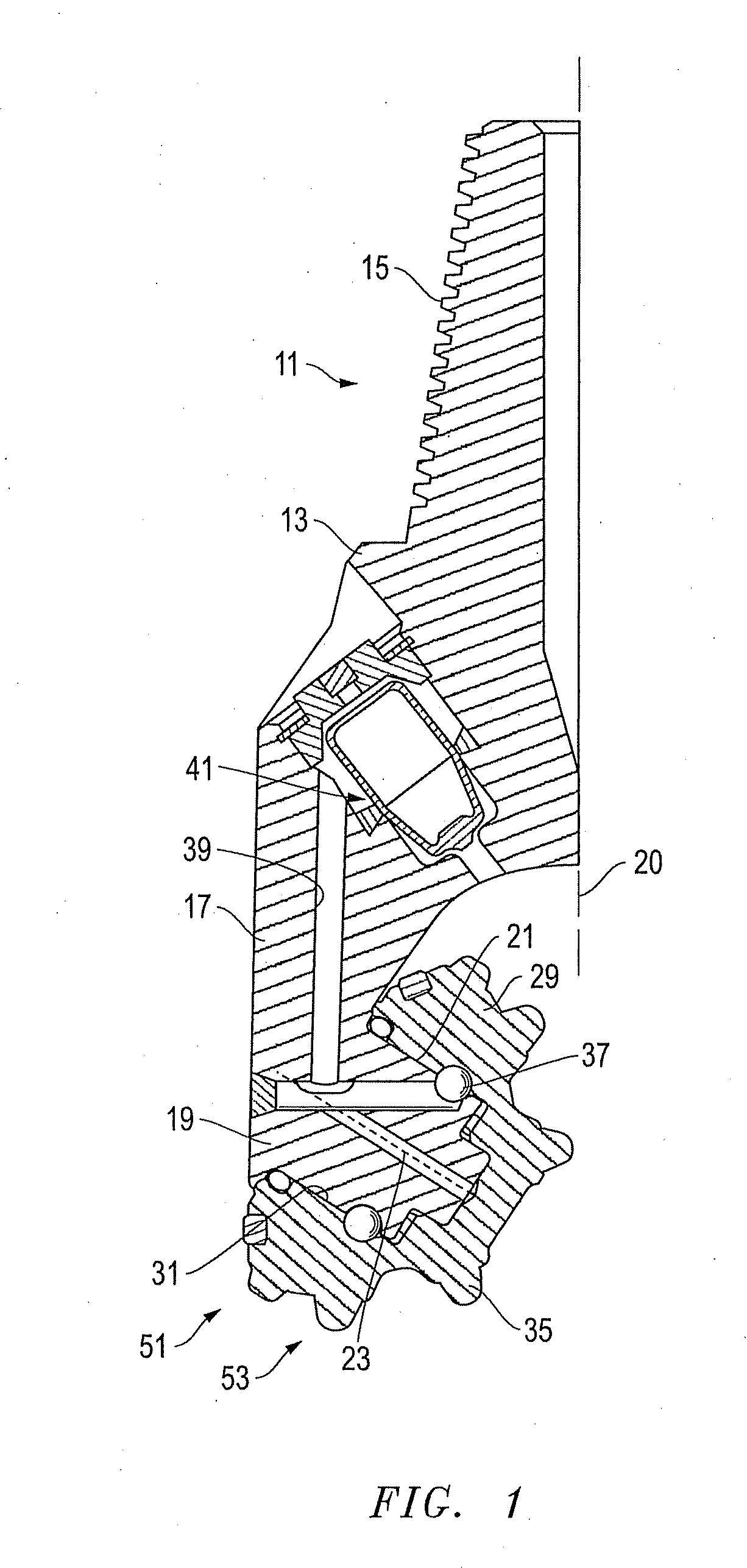
Referring to FIGS. 1-15, embodiments of an improved system, method, and apparatus for reducing the harmful effects of tracking with drill bits are disclosed. One embodiment of a bit 11 (FIG. 1) has a body 13 with a threaded shank 15 on its upper end for connection to a drill string (not shown). Body 13 typically has three bit legs 17 (only one shown), and each leg 17 has a depending bearing pin 19. Each bearing pin 19 inclines downward and inward toward an axis 20 of rotation of body 13. Each bearing pin 19 has a cylindrical surface 21 that is concentric with a bearing pin axis 23. A roller cone 29 is mounted to each pin 19 and has an axial cavity with a cylindrical portion 31 that fits around bearing surface 21 of pin 19. Roller cone 29 rotates on pin 19 about its roller cone axis, which coincides with bearing pin axis 23.

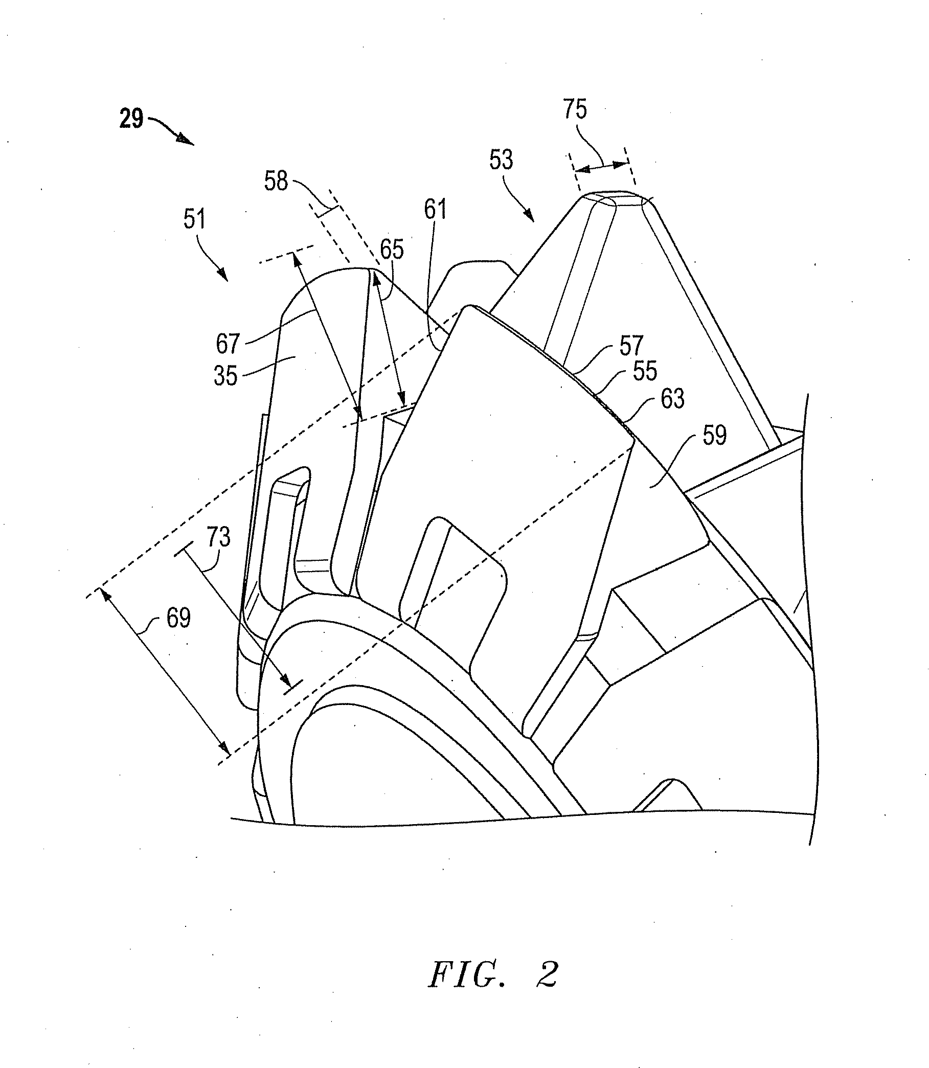
Each roller cone 29 has a plurality of cutting elements 36 (FIG. 1) on its exterior. Cutting elements 35 may be formed as steel teeth milled into the exterior sur...


PUM


Abstract

The harmful effects of tracking are reduced for a drill bit having roller cones with at least one of the outermost rows of active teeth containing one or more teeth having a height that does not extend to the height of at least one of the outermost rows on another roller cone on the bit. The crest on this tooth may have a length in a circumferential direction that is wider than an overall width of the tooth in the outer to inner direction. The invention may be used on any cutter row, not just the outermost row. The design may be used on a different roller cone or row, or more than one cutter row. The anti-tracking feature may be located between the leading and trailing edges of the tooth on one or more roller cones.

Description

BACKGROUND OF THE INVENTION1. Technical FieldThe present invention relates in general to drill bits and, in particular, to an improved system, method, and apparatus for reducing the harmful effects of tracking with drill bits.2. Description of the Related ArtA roller cone earth-boring drill bit has a number of cones, typically three, each of which is rotatably mounted to a bearing pin. Each cone rotates about its axis when the bit body rotates around the bit axis. The cones have cutting elements, often in rows, which may be teeth integrally formed in the cone metal, or tungsten carbide inserts pressed into mating holes in the cone metal.Each cone has an outermost or heel row near a gage surface of the cone and one or more inner rows. One or more of the cones have cutting elements located near or on the nose of the cone. In some cases the cutting elements in the adjacent row closest to the heel row will be staggered or alternate with the cutting elements in the heel row.The inner row...

Claims


Application Information

Patent Timeline
Patent Type & Authority Applications(United States)
IPC IPC(8): E21B10/16
CPCE21B10/16
Inventor BUSKE, ROBERT J.OVERSTREET, JAMES L.PESSIER, RUDOLF CARL
Owner BAKER HUGHES INC
Why Eureka
Try Eureka