Anchor

a technology of anchors and fixing rods, applied in the field of anchors, can solve the problems of greater distance between the eyes of the worker and the anchor, the anchor disclosed in the patent literature 1 is not suitable for fixing to the ceiling structure, and the tip portion of the steel bar is integrated with the tip portion of the ceiling structure, so as to achieve the effect of easy checking the placement condition of the anchor

Inactive Publication Date: 2011-12-29
ENUPATTO
View PDF0 Cites 6 Cited by
  • Summary
  • Abstract
  • Description
  • Claims
  • Application Information

AI Technical Summary

Benefits of technology

[0011]The worker relies heavily on his experience for management of the rotation torque. This easily causes unevenness of the placing quality of anchors, while making it difficult to find faulty placement even if it is generated.
[0027]As described above, the anchor of the present invention does not suffer from drop of the anchor bolt as the cone nut threadedly engages the shaft part of the anchor bolt. Further, during placement of the anchor, the base portion of the anchor bolt presses the expansion member in response to threaded insertion of the shaft part to cause the wing-like expansion parts to expand. So, the placement condition of the anchor can be checked by visually checking the expansion conditions of the expansion parts after the placement. Thus, the present invention makes it possible to check the placement condition of the anchor easily to realize efficient and safe check after the placement.

Problems solved by technology

The anchor disclosed in patent literature 1 is not suited for fixation to a ceiling structure.
So, if the ceiling structure is shaken strongly for example by an earthquake, the cone nut falls off the inside of the spreading sleeve, resulting in a fear of drop of the spreading sleeve integrated with the tip portion of the steel bar from the ceiling structure.
This process generates a problem as one cannot check to see visually if the head has caused the anchor socket to spread to its normal placement condition.
This placement process makes a distance between the eyes of the worker and the anchor greater, so visual check is made more difficult.
This easily causes unevenness of the placing quality of anchors, while making it difficult to find faulty placement even if it is generated.

Method used


Image

  • Anchor
  • Anchor
  • Anchor

Examples


first preferred embodiment

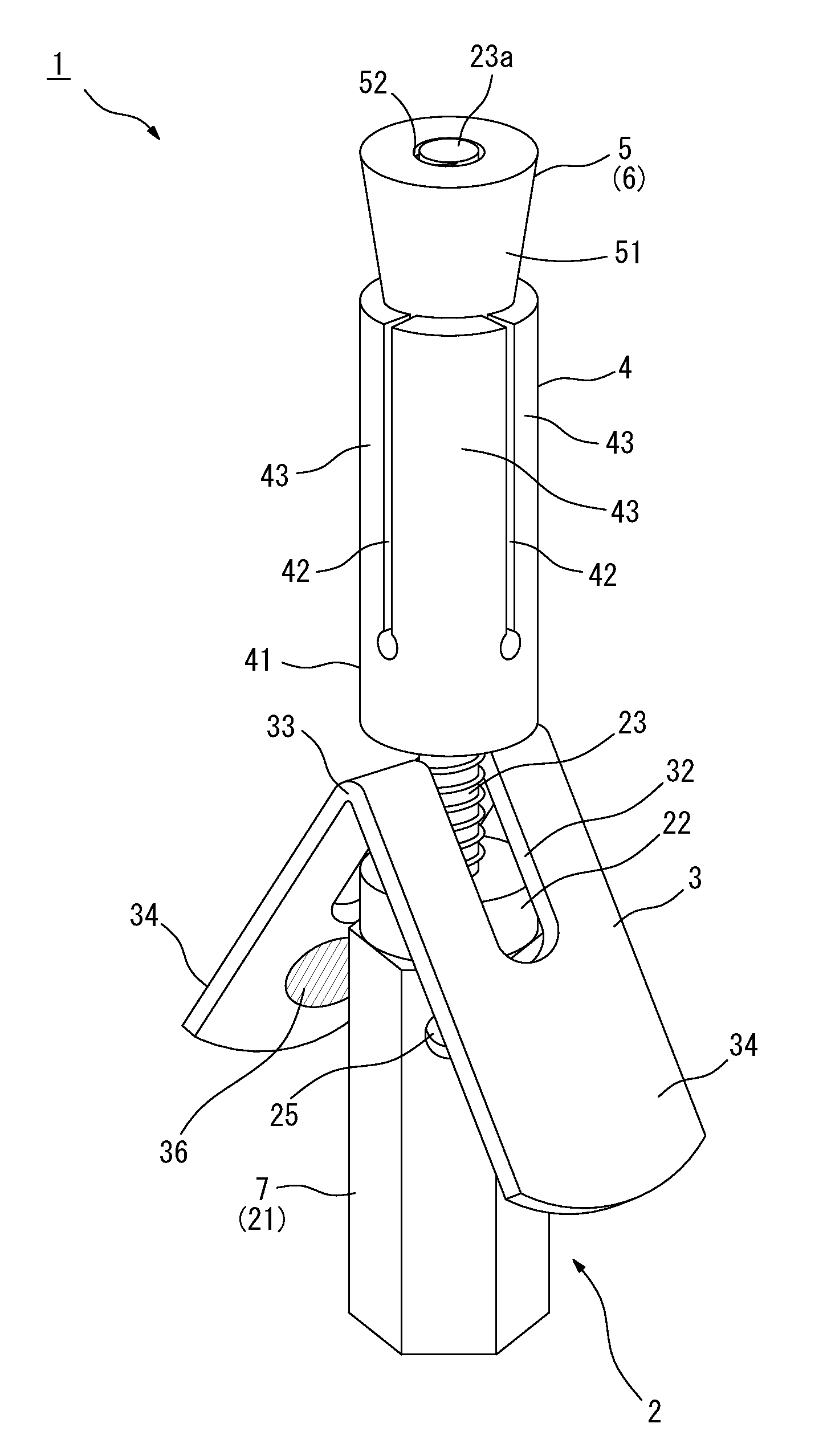
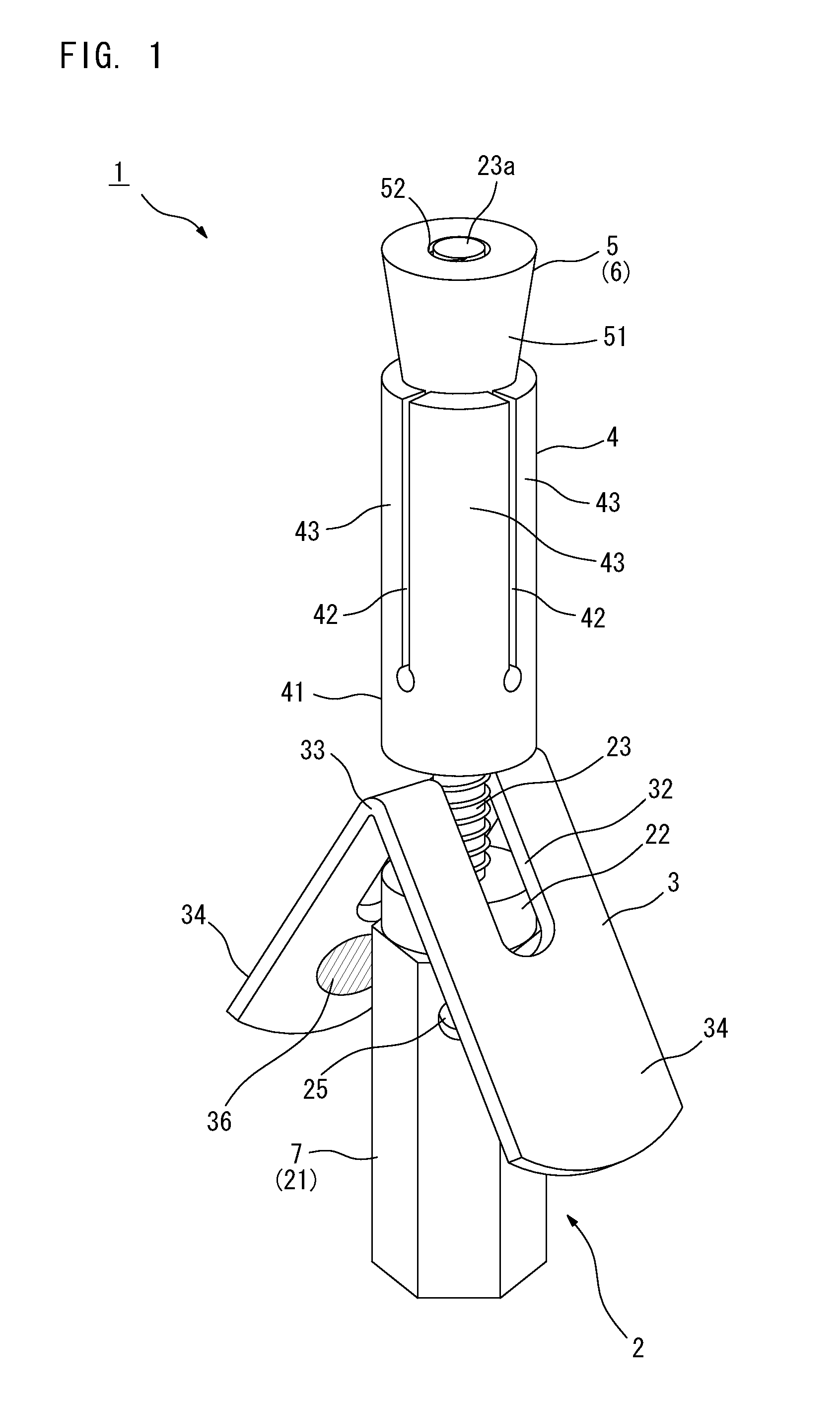
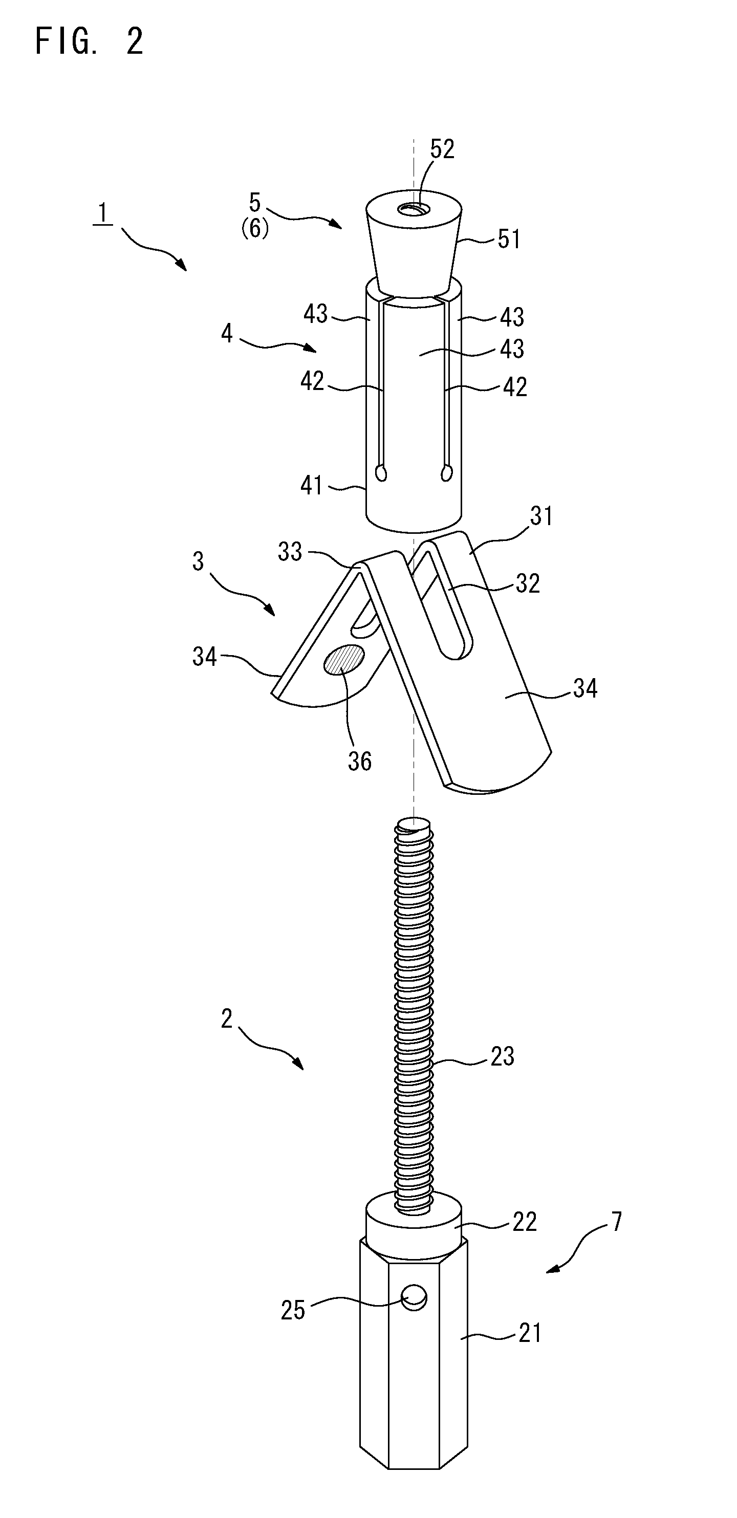
[0045]FIG. 1 is a perspective view showing an anchor 1 of a first preferred embodiment of the present invention with all parts of the anchor 1 assembled. FIG. 2 is a perspective view of the anchor 1 with all the parts of the anchor 1 separated. FIG. 3 is a longitudinal sectional view of the anchor 1 with all the parts of the anchor 1 assembled.

[0046]The anchor 1 of the first preferred embodiment includes an anchor bolt 2, a V-shaped expansion member 3, a spreading sleeve 4, and a cone nut 5. The anchor 1 is to be attached to various types of skeletons such as concrete buildings and structures, and is suited for attachment especially to ceiling structures.

[0047]The anchor bolt 2 includes a shaft part 23 of a predetermined length that has a tip portion with a male screw thread. The anchor bolt 2 also includes a rotation control section 7 at its base portion for causing the shaft part 23 to rotate. The rotation control section 7 is constructed of a prismatic nut part 21 of a predetermi...

second preferred embodiment

[0072]A second preferred embodiment of the present invention is described next. FIG. 9 is a perspective view of an anchor 1a of the second preferred embodiment with all parts of the anchor 1a separated. As shown in FIG. 9, the anchor 1a of the second preferred embodiment includes an anchor bolt 2, a V-shaped expansion member 3, a spreading sleeve 4, and a nut member 27. Like the anchor 1 described above, the anchor 1a is to be attached to various types of skeletons such as concrete buildings and structures, and is suited for attachment especially to ceiling structures. The anchor 1a of the second preferred embodiment differs from the anchor 1 of the first preferred embodiment in that the anchor bolt 2 and a rotation control section 7 have different structures. The structures of the expansion member 3 and the spreading sleeve 4 are the same as those of the first preferred embodiment. The difference of the second preferred embodiment from the first preferred embodiment is described be...

third preferred embodiment

[0081]A third preferred embodiment of the present invention is described next. The main structure of the anchor of the third preferred embodiment is substantially the same as that of the anchor 1 of the first preferred embodiment. The difference of the anchor 1 of the third preferred embodiment from one of the first preferred embodiment is a deformable material 9 provided at the bottom portion of the screw hole 24 defined in the anchor bolt 2.

[0082]FIG. 12 is a perspective view showing an enlarged view of the nut part 21 of the anchor bolt 2 of the third preferred embodiment. As described above, the closed-end screw hole 24 is defined at the lower end surface of the nut part 21. Further, the through hole 25 communicatively coupled to the bottom portion and its vicinity of the screw hole 24 is defined in the side surface of the nut part 21 of the anchor bolt 2. A part 92 made of a shaped resin which has flexibility such as polypropylene is attached to the bottom portion of the screw ...


PUM


Abstract

The present invention is intended to provide an anchor that makes it possible to check the placement condition of the anchor easily to realize efficient and safe check after the placement. An anchor includes an expansion member that permits a shaft part to pass therethrough while being placed between a base portion of an anchor bolt and a spreading sleeve. The expansion member includes wing-like expansion parts that are caused to expand by pressing force exerted in the axial direction of the shaft part. The anchor bolt causes the shaft part to rotate in response to the rotation of the base portion of the anchor bolt, thereby driving a cone nut into the spreading sleeve. As a result, spreading parts spread outwardly. Further, the base portion of the anchor bolt presses the expansion member in response to threaded insertion of the shaft part to cause the wing-like expansion parts to expand.

Description

[0001]This application is based on the applications No. 2010-143614 and No. 2011-117966 filed in Japan, the contents of which are hereby incorporated by reference.BACKGROUND OF THE INVENTION[0002]1. Field of the Invention[0003]The present invention relates to an anchor to be attached to various types of skeletons such as concrete buildings and structures, and more specifically, relates to an anchor that is suited for attachment to ceiling structures.[0004]2. Background Art[0005]In order to attach hanging objects such as air conditioners, lighting fixtures, and various types of pipes to an existing ceiling structure of a building such as that made of concrete, anchors intended to support the hanging objects are fixed to the ceiling structure. Conventionally known anchors used for this purpose are disclosed for example in Japanese Patent Application Laid-Open No. 10-231583 (1998) (patent literature 1), and in Japanese Patent Application Laid-Open No. 10-110475 (1998) (patent literatur...

Claims


Application Information

Patent Timeline
Patent Type & Authority Applications(United States)
IPC IPC(8): F16B13/00F16B13/06
CPCF16B13/068
Inventor IKUNO, MAKOTO
Owner ENUPATTO
Why Eureka
Try Eureka