
Thermal energy steering device

Active Publication Date: 2012-01-05
TOYOTA MOTOR CO LTD
View PDF5 Cites 6 Cited by
  • Summary
  • Abstract
  • Description
  • Claims
  • Application Information

AI Technical Summary

Benefits of technology

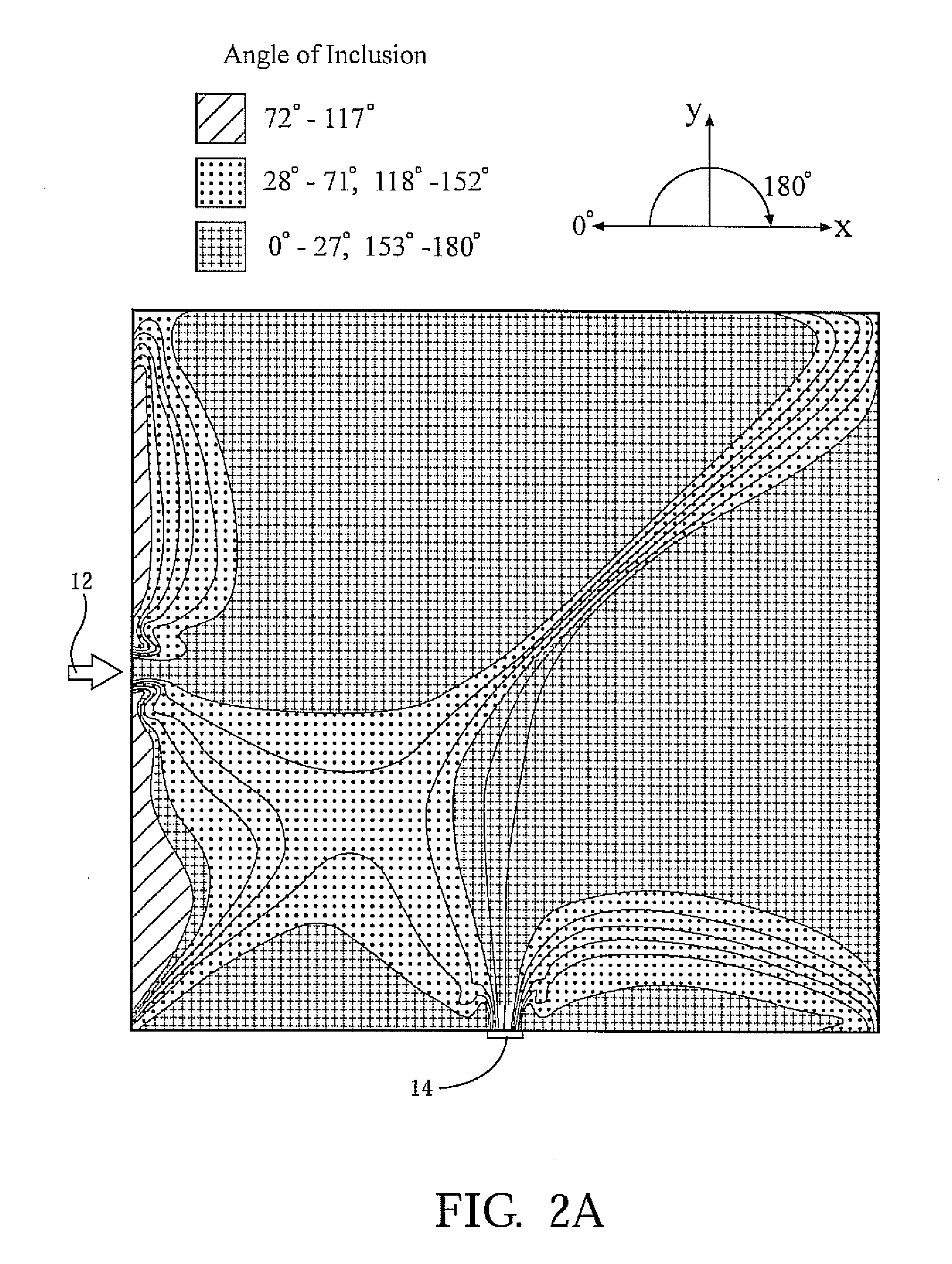
[0005]According to another embodiment of the invention, a method for optimizing the orientation of a plurality of thermally conductive inclusions so as to steer thermal flux from a thermal energy source to a desired location is provided. The method includes the step of identifying the location of the thermal energy source and establishing a desired location for concentrating thermal flux. The thermally conductive inclusions are oriented within the matrix so as to minimize thermal resistance between the thermal source and the desired location.

Problems solved by technology

In some instances the thermal flux may be adverse and cause nearby components to malfunction.
However, thermal energy is often lost by dissipation into the environment prior to storage into the thermal energy sink.

Method used


Image

  • Thermal energy steering device
  • Thermal energy steering device
  • Thermal energy steering device

Examples


Embodiment Construction

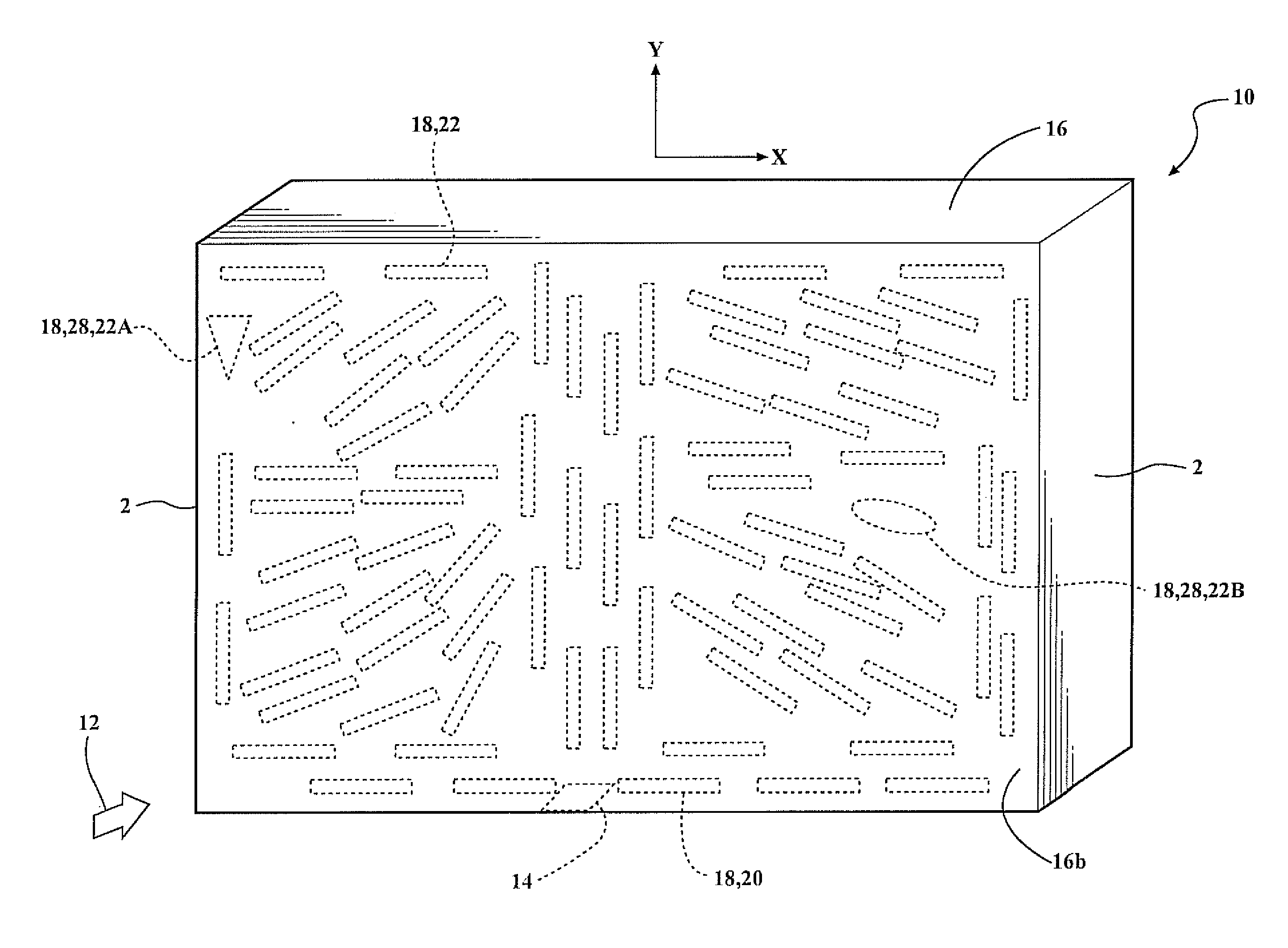
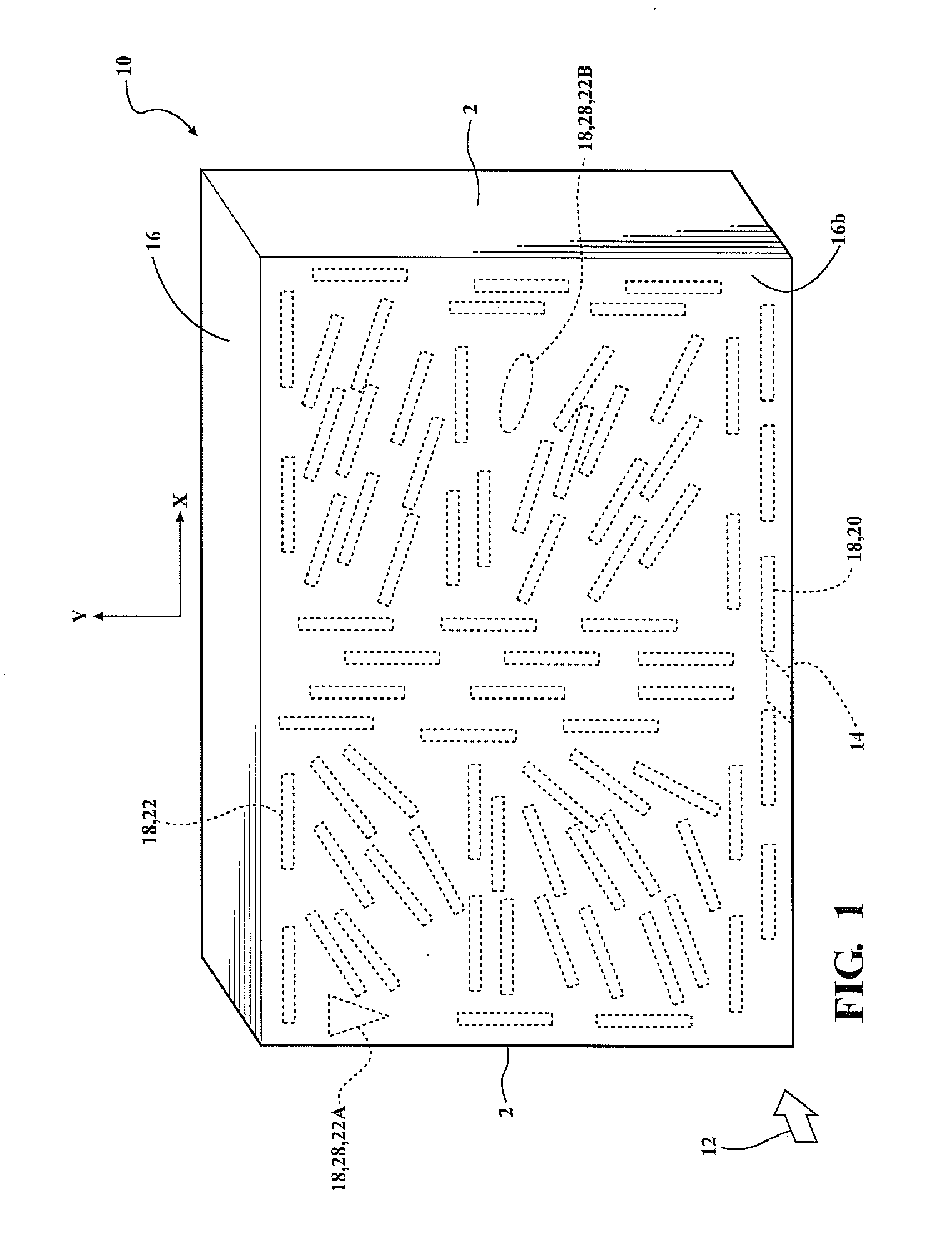
[0019]Referring to the Figures, a thermal flux steering device, also referenced by those in the art as a composite material, 10 for steering thermal flux to a predetermined location is provided. The thermal flux steering device 10 is operable to receive thermal flux from a thermal energy source 12 and steer the thermal energy to a desired location such as a thermal energy sink 14 for later harvesting. The thermal flux steering device 10 includes a matrix 16 impregnated with a plurality of thermally conductive inclusions 18. The thermally conductive inclusions 18 are oriented within the matrix 16 so as to steer or concentrate the thermal flux into a predetermined location.

[0020]With reference now to FIG. 1, a perspective view of the matrix 16 is provided. The matrix 16 is formed of material operable to hold and position the thermally conductive inclusions 18 at a predetermined angle. Such a material is currently known and used in the art and illustratively includes cyanate-ester resi...


PUM


Abstract

A thermal flux steering device and method for steering thermal flux into a concentrated area is provided. The thermal flux steering device includes a matrix impregnated with a plurality of thermally conductive inclusions. The thermally conductive inclusions are angled so as to steer thermal flux into a concentrated area such as a thermal energy sink in communication with the matrix. The thermally conductive inclusions may be filler fibers or thermally conductive particles impregnated within the matrix. Orientation of the thermally conductive inclusions may be determined by detecting the thermal flux of the thermal energy source, the thermodynamic properties of the matrix and the thermally conductive inclusions, and the location of the flux concentration area.

Description

FIELD OF THE INVENTION[0001]The present invention relates to a device for steering thermal flux. More particularly the invention relates to a device such as a composite material, having a matrix impregnated with a plurality of thermally conductive inclusions. The thermally conductive inclusions are angled so as to steer thermal flux to a predetermined location within the device.BACKGROUND OF THE INVENTION[0002]Many devices are subject to thermal flux, such as electronics, motors, internal combustion engines, and the like. The thermal flux is often dissipated into the environment. In some instances the thermal flux may be adverse and cause nearby components to malfunction. Accordingly, ancillary devices such as a fan are often used to cool the source and the nearby components. In other instances, a thermal energy sink (e.g. a thermoelectric device) is used to store the thermal energy for later use. However, thermal energy is often lost by dissipation into the environment prior to sto...

Claims


Application Information

Patent Timeline
IPC IPC(8): F28F27/02F28F7/00
CPCF28D2021/0029F28F2013/006H01L35/30F28F13/00H10N10/13
Inventor DEDE, ERCAN MEHMET
Owner TOYOTA MOTOR CO LTD
Learn More