

Excavation apparatus
- Summary
- Abstract
- Description
- Claims
- Application Information
AI Technical Summary
Benefits of technology
Problems solved by technology
Method used
Image

Examples
Embodiment Construction
[0044] Referring now to the drawings, like reference numerals designate identical or corresponding parts throughout the several views.
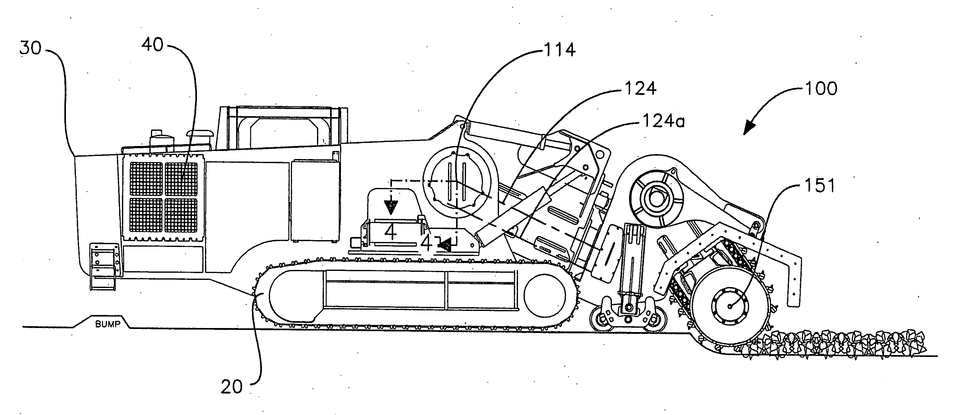
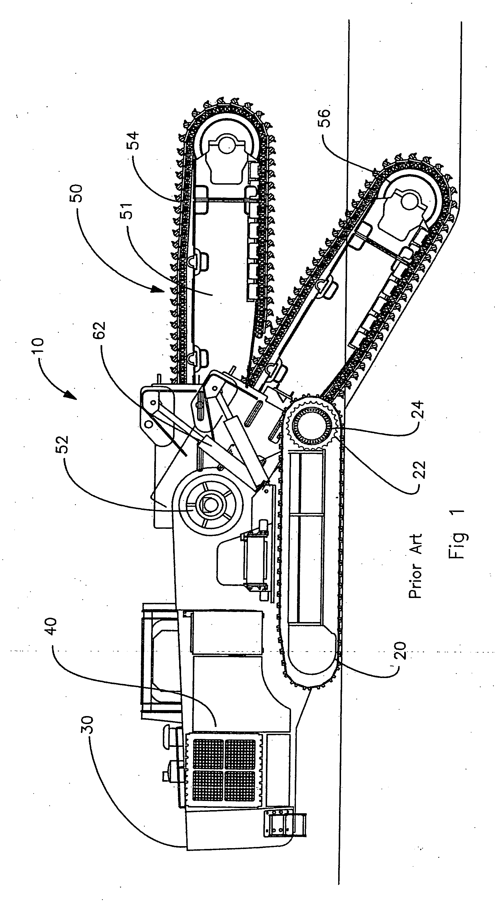
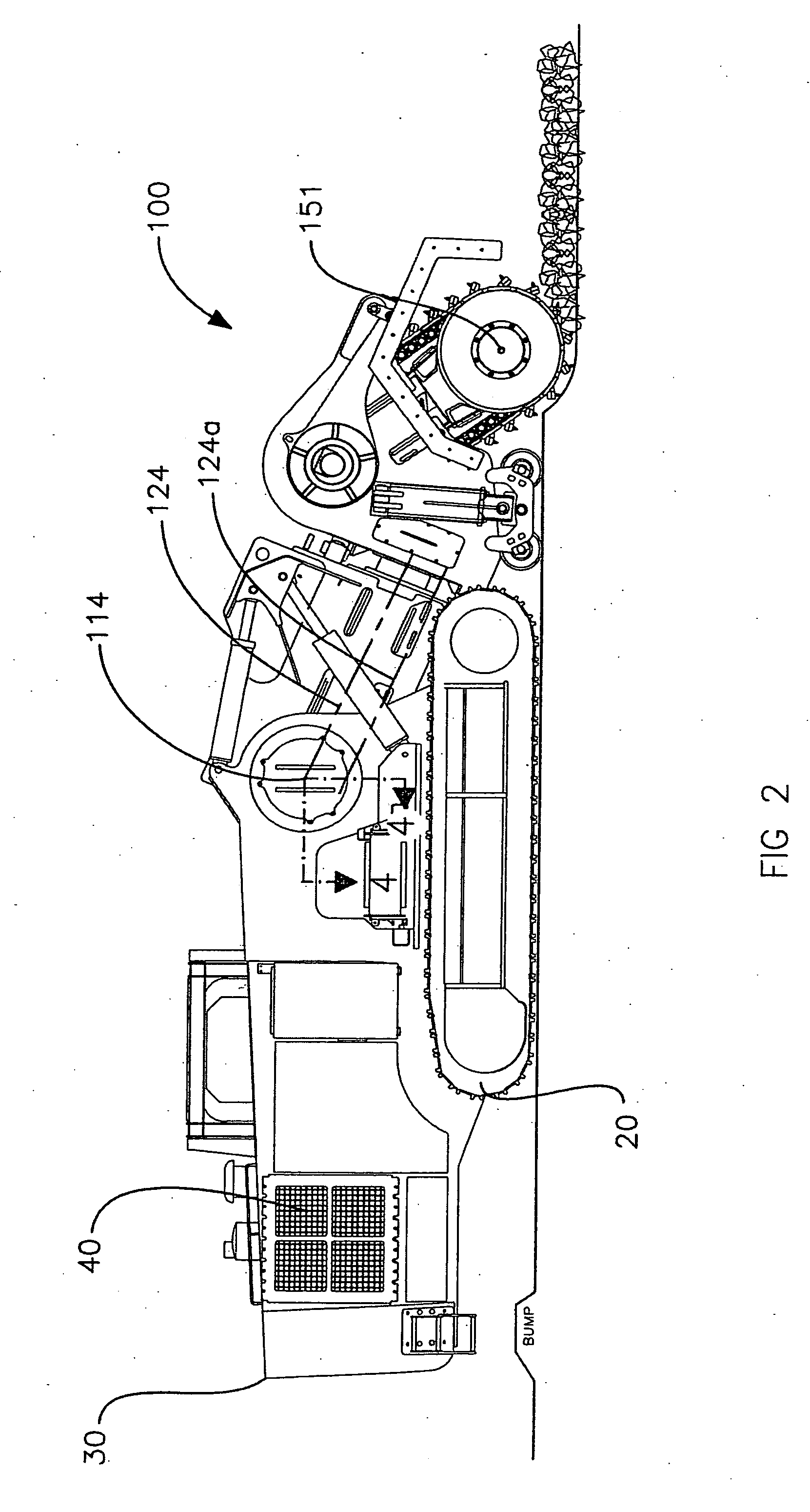
[0045] The current invention includes a track trencher with a new excavation boom. A preferred embodiment is illustrated in FIGS. 2 and 3. In FIG. 2 the track trencher includes the basic components of the main frame 30, track assemblies 20, power unit 40; all with similar functions as described for the prior art track trencher. The excavation boom is replaced by a new excavation boom 100 of the present invention.
[0046] The new excavation boom 100 is illustrated in FIG. 3 and includes a mounting section 110, swivel 120 and head unit 130. The mounting section 110 includes a mount frame 112 that will mate with the main frame 30 as illustrated in FIG. 4 and FIG. 5. The main frame 30 includes two coaxial holes with an array of tapped bolt holes, bolt patterns 32, which define the main pivot axis 114. Bolt pattern 32 is defined as including both the large...
PUM
 Abstract
Description
Claims
Application Information