
Microfluidic chip for analysis for fluid sample

Active Publication Date: 2012-01-05
NANOENTEK
View PDF2 Cites 1 Cited by
  • Summary
  • Abstract
  • Description
  • Claims
  • Application Information

AI Technical Summary

Benefits of technology

[0019]As described above, the microfluidic chip in accordance with the present invention is designed to prevent the fluid sample from leaking to the extension portion upon the introduction of the sample into the microchannel so as to afford a sufficient wall-free effect to the extension portion. Also, the microfluidic chip according to the present invention allows the sample to reside in the reaction portion long enough to react with reagents and to exert a sufficient mixing effect.
[0020]Therefore, the microfluidic chip of the present invention guarantees accurate and quick qualitative and quantitative analyses of a trace amount of a sample without volumetric loss.

Problems solved by technology

In the case of a chip using capillary phenomenon as a main driving force, the fluid flowing through the microchannels shows irregular and non-uniform mobility patterns, particularly when the microchannels are of extremely low height or are narrowed.
These irregular and non-uniform mobility patterns are generated due to the differences in fluid interaction with upper and lower walls and with left and right walls and act as a great hindrance to detecting and analyzing a target contained in a trace amount in the fluid sample.
Also, when closed channels of tens of micrometers in size are formed, it is not easy to uniformly process edge portions of channels without loss, thus causing problems in dimension and quality upon mass-scale production.
This minute difference in channel structure disturbs fluid flow, leading to an inconsistent analysis result.
Thus, it impedes the wall-free effect suggested by Korean Patent Application No. 10-2007-0073659, resulting in the bringing of errors into the analysis results.
Therefore, unless the flow of the fluid across the reaction portion is controllably delayed during passage therethrough, an error may occur in the qualitative and quantitative analyses of a target within the fluid.

Method used


Image

  • Microfluidic chip for analysis for fluid sample
  • Microfluidic chip for analysis for fluid sample
  • Microfluidic chip for analysis for fluid sample

Examples


embodiment 1

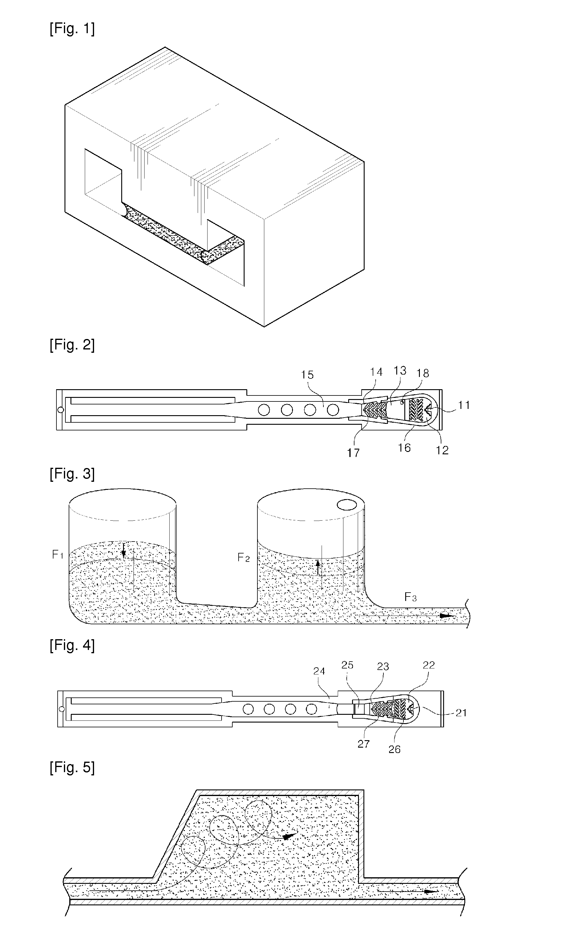
[0031]A microfluidic chip for analyzing fluidic samples in accordance with a first embodiment of the present invention, as shown in FIG. 2, has a channel structure comprising a sample inlet 11 for feeding a sample therethrough, a first reservoir 12 for primarily storing the sample therein, a second reservoir 13 for secondarily storing the sample therein, a first reaction portion 14 in which a target is conjugated with a label, and a second reaction portion 15 in which the labeled target undergoes a specific reaction, for example, an antigen-antibody reaction.

[0032]In this channel structure, the first reservoir is a chamber for accommodating the fluidic sample fed through the inlet and the second reservoir is also a chamber for storing the sample secondarily. From the second reservoir, the sample is moved through a wall-free microchannel leading to a reaction portion. A suitably controlled height of the microchannel allows noise of the sample to be filtered off without the use of pap...

embodiment 2

[0039]With reference to FIG. 4, a microfluidic chip for analyzing liquid samples in accordance with a second embodiment of the present invention will be described as shown. As seen in FIG. 2, the microfluidic chip has a channel structure comprising a sample inlet 21 for feeding a sample therethrough, a first reservoir 22 for primarily storing the sample therein, a first reaction portion 23 in which a target is conjugated with a label, a second reaction portion 24 in which the labeled target undergoes a specific reaction, for example, an antigen-antibody reaction, and a delaying portion 25, located between the first and the second reaction portions, for decreasing the flow rate of the sample.

[0040]In this embodiment, after being fed through the inlet and filling the reservoir, the sample flows into the first reaction portion through the wall-free microchannel. Then, when the sample immediately advances from the first reaction portion for the labeling reaction to the second reaction p...

embodiment 3

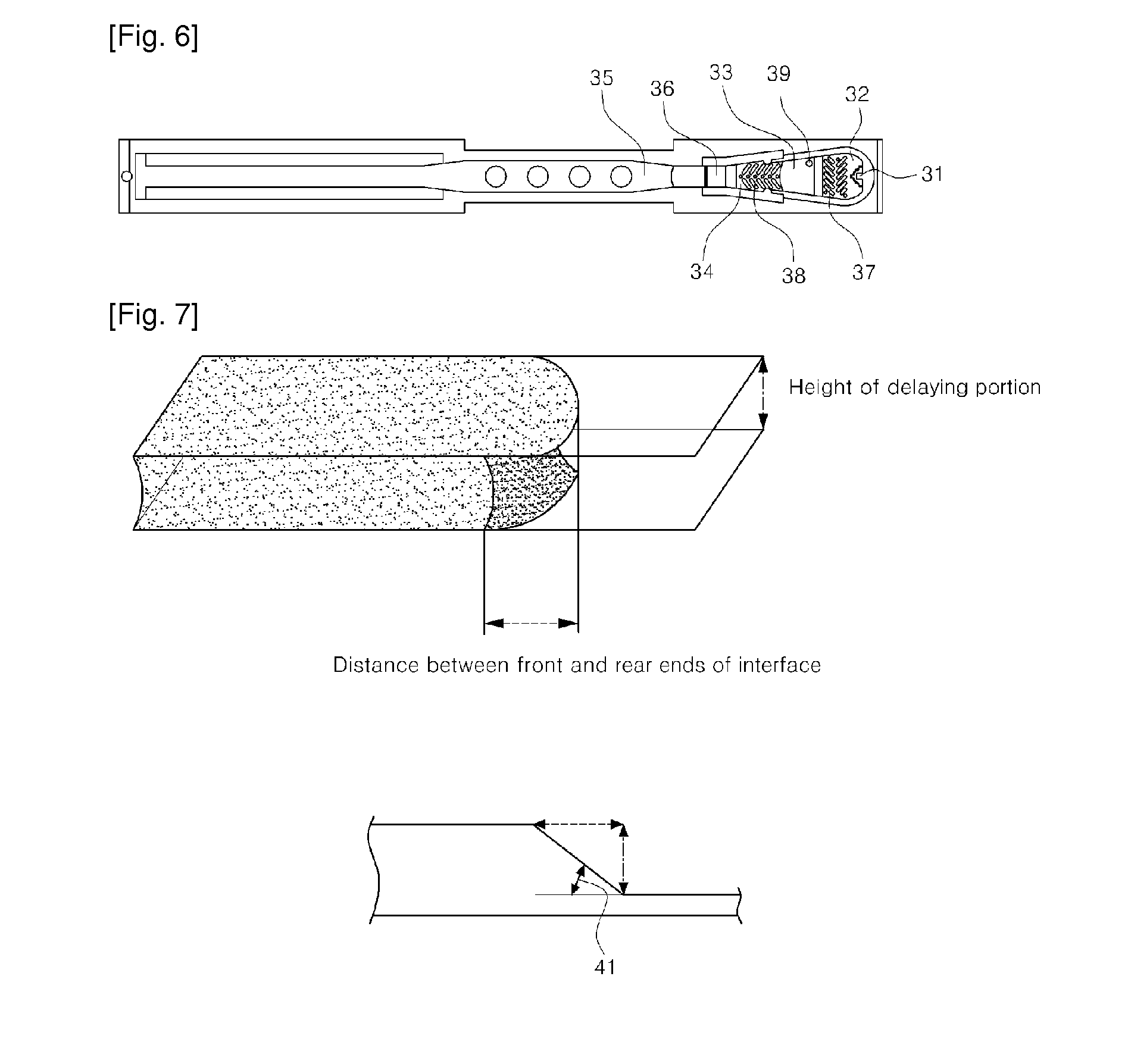
[0046]As shown in FIG. 6, a microfluidic chip for analyzing fluid samples in accordance with the present invention has a channel structure comprising a sample inlet 31 for feeding a sample therethrough, a first reservoir 32 for primarily storing the sample therein, a second reservoir 33 for secondarily storing the sample therein, a first reaction portion 34 in which a target is conjugated with a label, a second reaction portion 35 in which the labeled target undergoes a specific reaction, for example, an antigen-antibody reaction, and a delaying portion 36, located between the first and second reaction portions, for decreasing the flow rate of the sample.

[0047]This embodiment, resulting from the combination of the first and second embodiments, is adapted to prevent the sample flowing to the microchannel of the reaction portion from leaking to the extension portion thanks to the provision of the second reservoir and to delay the passage of the sample through the reaction portion than...


PUM


Abstract

Disclosed is a microfluidic chip capable of accurately and quickly detecting presence of a trace amount of a target within a fluid sample. It has a channel structure comprising a sample inlet for feeding a sample therethrough, a first reservoir for primarily storing the sample therein, a second reservoir for secondarily storing the sample therein, a first reaction portion in which a target is conjugated with a label, a second reaction portion in which the labeled target undergoes a specific reaction, such as an antigen-antibody reaction, and a delaying portion, located between the first and the second reaction portion, for decreasing a flow rate of the sample.

Description

TECHNICAL FIELD[0001]The present invention relates to a microfluidic chip capable of accurately and quickly detecting presence of a trace amount of a target within a fluid sample. More particularly, the present invention relates to a microfluidic chip for the analysis of a fluid sample, having a channel structure comprising a sample inlet for feeding a sample therethrough, a first reservoir for primarily storing the sample therein, a second reservoir for secondarily storing the sample therein, a first reaction portion in which a target is conjugated with a label, a second reaction portion in which the labeled target undergoes a specific reaction, such as an antigen-antibody reaction, and a delaying portion, located between the first and the second reaction portion, for decreasing a flow rate of the sample.BACKGROUND ART[0002]The analysis of fluid samples is widely used in the chemical and bioengineering fields as well as in the medical field to clinically diagnose diseases using blo...

Claims


Application Information

Patent Timeline
IPC IPC(8): B01L3/00C12M1/00
CPCB01L3/502723B01L3/502746B01L2300/0825B01L2300/087G01N2035/00158B01L2400/0406B01L2400/086G01N33/5304G01N35/00029B01L2300/089G01N33/48G01N33/50G01N33/53G01N35/00
Inventor LIM, HYUN CHANGPARK, JUN HALEE, CHANG SEOPJUNG, HYUN JOOPARK, JI YOUNGCHUNG, CHAN ILCHANG, JUN KEUN
Owner NANOENTEK
Learn More