

Lighting apparatus
a technology of light-emitting devices and light-emitting devices, which is applied in the direction of light-emitting devices for light sources, point-like light sources, lighting and heating devices, etc., can solve the problems of insufficient methods for inability to fully evaluate the effect of making colors look vivid, and pale red color
- Summary
- Abstract
- Description
- Claims
- Application Information
AI Technical Summary
Benefits of technology
Problems solved by technology
Method used
Image

Examples
second embodiment
[0105]FIGS. 8 and 9 are related to the present invention, where FIG. 8 shows a flowchart for determining a color gamut area ratio and the like and FIG. 9 is an explanatory diagram for illustrating characteristics of a lighting apparatus designed according to the flowchart in FIG. 8.
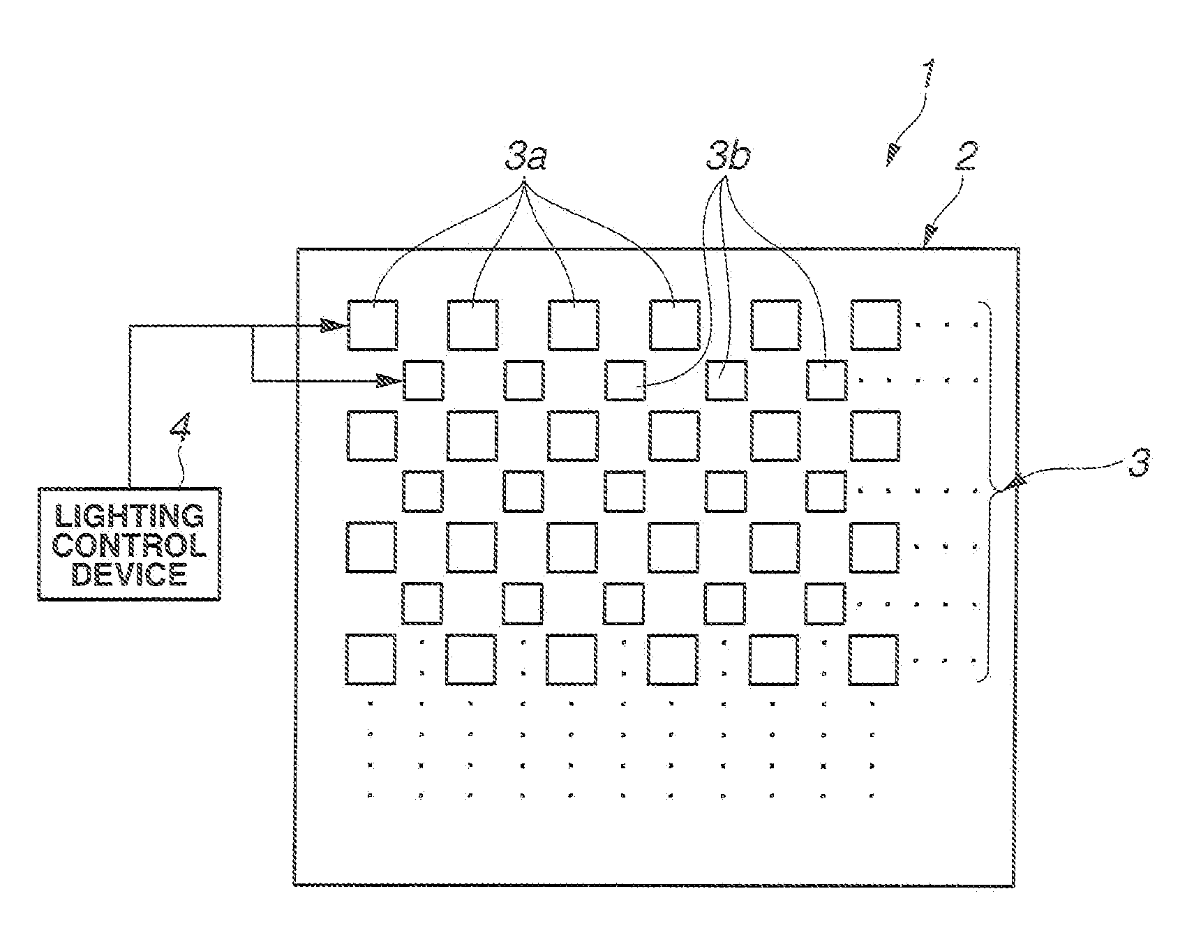
[0106]The present embodiment allows the color gamut area ratio, average color rendering index (Ra), and efficiency to be designed to desired values for a lighting apparatus configured as shown in FIG. 1.
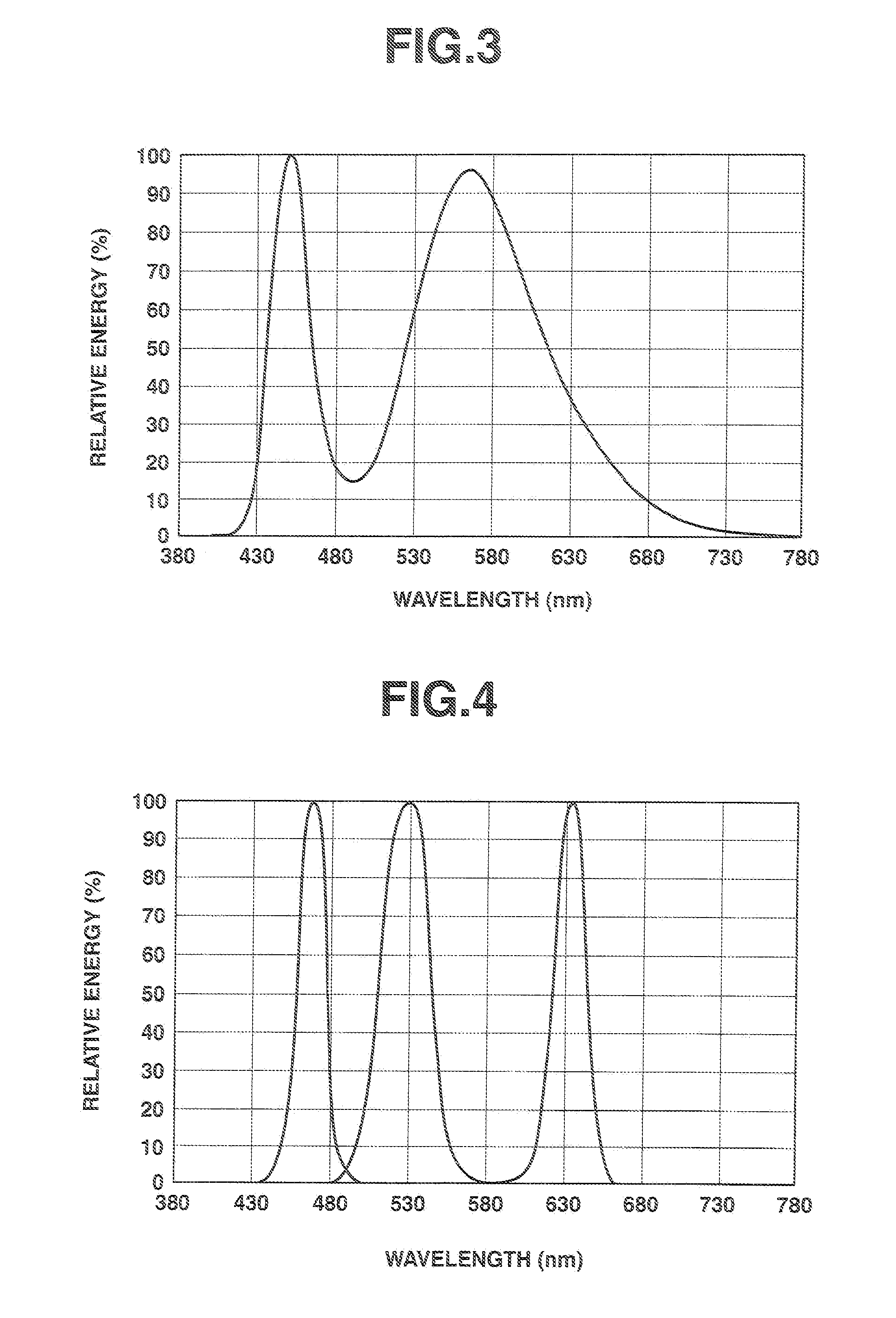
[0107]As described above, even if illumination has the same correlated color temperature and average color rendering index (Ra), the color of light can be made to look much more vivid if the color gamut area ratio is set appropriately. The color gamut area ratio can be controlled by setting the light mixing ratios (luminous flux ratios) appropriately among the LEDs of different colors.
[0108]According to the present embodiment, again a light source device includes four LEDs in total: a white LED made up of ...
third embodiment
[0131]FIGS. 10 and 11 are related to the present invention, where FIG. 10 is a block diagram showing a schematic configuration of a light source device and FIG. 11 is an explanatory diagram showing external appearance of a lighting apparatus incorporating the light source device shown in FIG. 10.
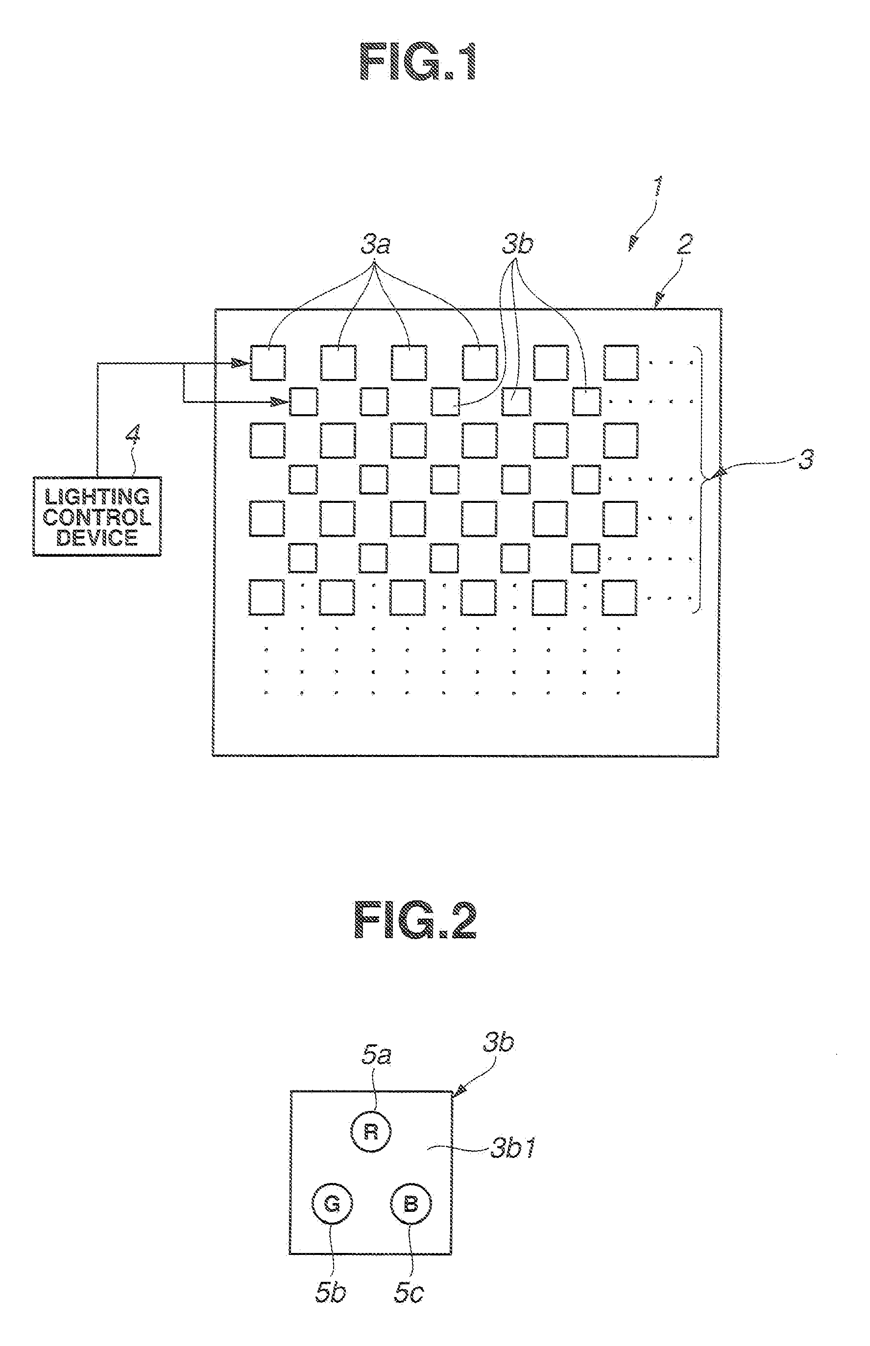
[0132]A substrate 100 shown in FIG. 10 is placed in an enclosure 110 shown in FIG. 11. A plurality of red LEDs, green LEDs, blue LEDs, and white LEDs are disposed on the substrate 100. A lighting control device (not shown) used to turn on the LEDs is disposed in the enclosure 110. The LEDs and the lighting control device are supplied with electric power through a cap 111. A diffuser plate 112 is attached to the enclosure 110 and emergent light from the LEDs in the enclosure 110 is designed to be discharged via the diffuser plate 112.
[0133]In the light source device according to the present embodiment, a plurality of white LEDs 105 configured to emit a first white light as well as a plurality...
fourth embodiment
[0138]FIGS. 12 and 13 are related to the present invention and are explanatory diagrams showing a schematic configuration of a lighting apparatus, where FIG. 12 shows a planar shape of a light source device while FIG. 13 shows a sectional shape of the light source device and part of a lighting control device. Incidentally, external appearance of the lighting apparatus incorporating the light source device according to the present embodiment is the same as in FIG. 11, and thus diagrammatic illustration thereof is omitted.
[0139]As described above, by controlling the light mixing ratio among LEDs of different colors, it is possible to construct a lighting apparatus having a desired correlated color temperature and a desired color gamut area ratio Ga. However, luminous flux reduction due to heat and aged deterioration of chip material vary from LED to LED, so illumination based on light mixing could undergo changes in colors of light with the passage of time.
[0140]Thus, the present embo...
PUM
 Abstract
Description
Claims
Application Information