Fastening tool

a technology of fastening and tool, which is applied in the direction of wrenches, screwdrivers, metal-working hand tools, etc., can solve the problems of loosing bolts and nuts, and affecting the performance of bolts and nuts

Inactive Publication Date: 2012-01-19
AOYAMA SEISAKUSHO CO LTD
View PDF1 Cites 8 Cited by
  • Summary
  • Abstract
  • Description
  • Claims
  • Application Information

AI Technical Summary

Benefits of technology

[0009]The present invention is finished by aiming to provide a fastening method and a fastening tool which solves the problems as mentioned above, securely and stably generates an axial force, prevents a bolt and a nut from being loosened due to a repeated load or vibration, does not require to apply a friction coefficient stabilizing agent to a thread ridge of the bolt, can be reused without any complicated detaching work, does not require to set a height of the nut high, and does not require any rust proofing countermeasure.

Problems solved by technology

Accordingly, it is necessary to securely store the axial force in the shaft of the bolt, however, about 90% of a fastening torque is lost due to a friction between a seat surface of the nut and the fastened member and a friction of the thread surface at a time of screwing and fastening the nut to the bolt, and only about 10% of the fastening torque can store the axial force in the shaft of the bolt.
As mentioned above, since it is impossible to sufficiently store the axial force in the shaft of the bolt, there has been a problem that the bolt and the nut are loosened due to a repeated load and a vibration applied to the fastened member.
Further, there are risks that the friction force between the seat surface of the nut and the fastened member and the friction force of the threaded portions are scattered, and the seat surface of the nut and the fastened member, and the threaded portions are gnawed or seized, whereby the axial force stored in the shaft of the bolt is not stable, and the bolt and the nut are loosened.
Therefore, there is a problem that a cost is increased.
However, in accordance with this non-assemble swage fastening method, since it is necessary to break the pin 51 and the collar 53 by the special tool at a time of detaching, there is a problem that the pin 51 and the collar 53 can not be reused, as well as a detaching work becomes complicated.
However, since the collar 63 is caulked so as to be fastened, there has been a problem that the once detached collar 63 can not be reused.
Further, in the axial force fastening method, since the collars 53 and 63 are caulked, a surface treated layer such as a plating or the like applied to the surfaces of the collars 53 and 63 is scratched, and there has been a problem that a rust proofing countermeasure is necessary.

Method used


Image

  • Fastening tool
  • Fastening tool
  • Fastening tool

Examples


first embodiment

[0051]A description will be given below of a preferable embodiment (a first embodiment) of the present invention with reference to the accompanying drawings.

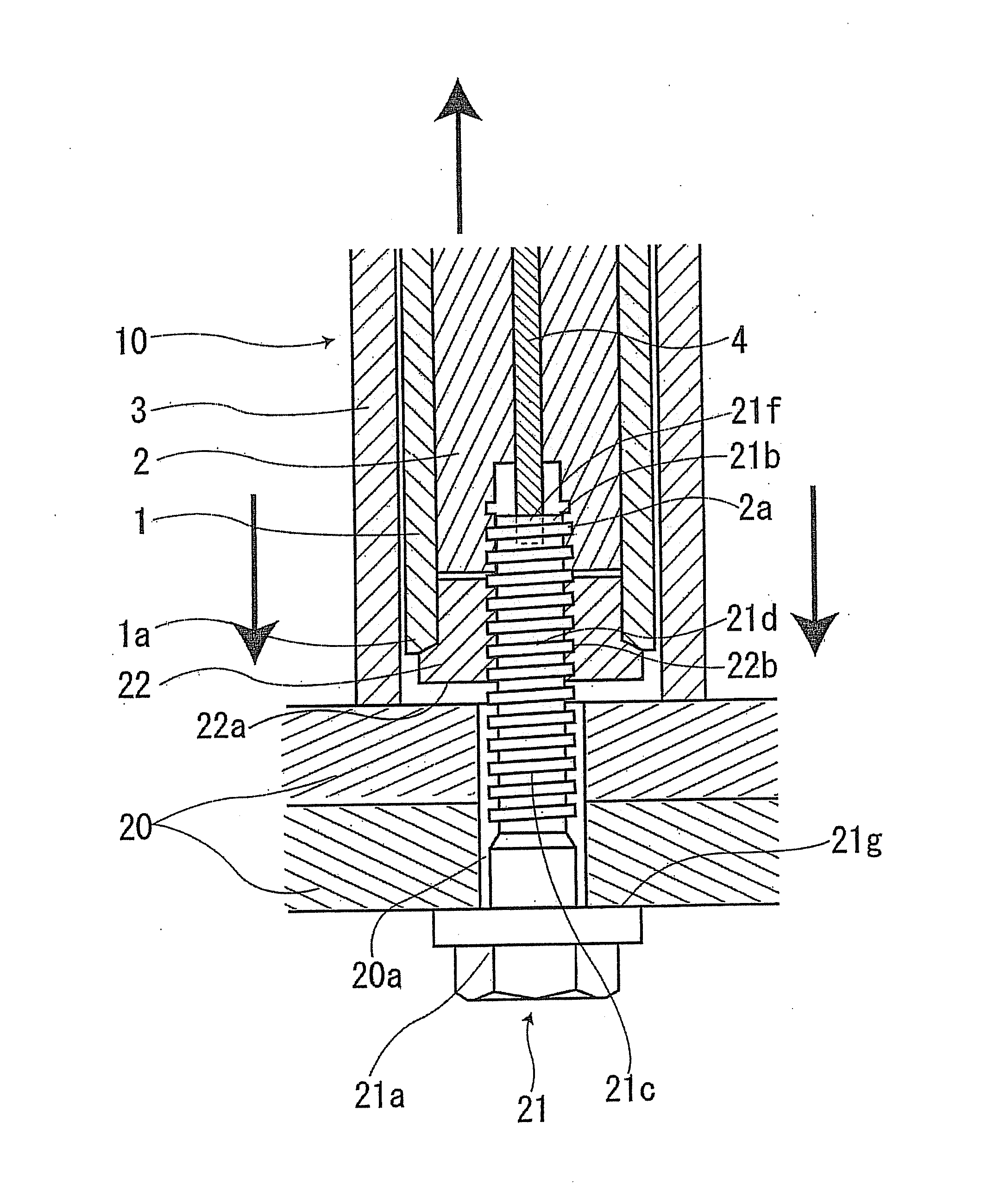
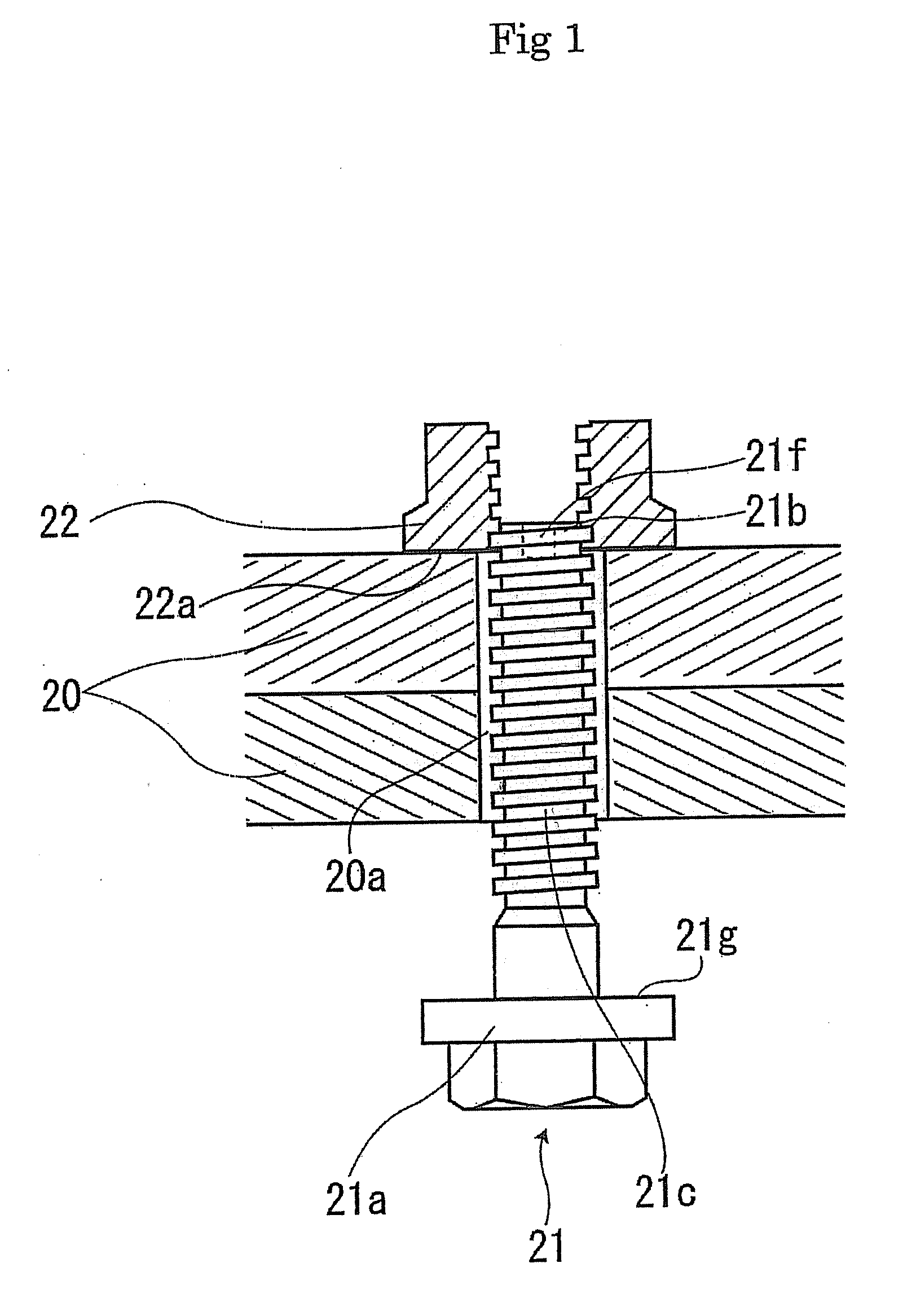
[0052]An engagement concave portion 21f depressed in as a hexagonal shape or the like is provided in a leading end of a shaft portion 21c of a bolt 21 used in the present invention. In this case, a nut 22 in accordance with the embodiment is constituted by a hexagonal nut. However, the nut 22 is not limited to the hexagonal nut, but may be constituted by any nut such as a square nut, a dodecagonal nut, a torque nut.

[0053]The bolt 21 is passed through a hole 20a of a fastened member 20, and the nut 22 is lightly fastened to a leading end 21b of the bolt 21 (a state in FIG. 1).

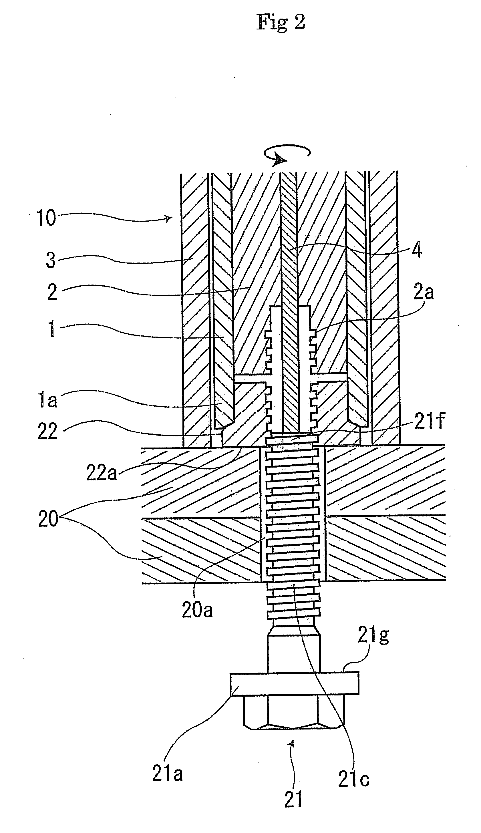
[0054]A fastening tool 10 used in the present invention is mainly constituted by a tubular fastening member 1, a spindle member 2 stored in an inner portion of the fastening member 1, an inner member 4 stored in an inner portion of the spindle member 2, and ...

second embodiment

[0063]Next, FIG. 8 shows an explanatory view showing a second embodiment, and a description will be given of the second embodiment. In this second embodiment, a normal bolt 23 is used. In this case, the normal bolt 23 means a bolt in which the engagement concave portion 21f (the first embodiment) is not formed in the leading end of the shaft portion of the bolt.

[0064]The bolt 23 is passed through the hole 20a of the fastened member 20, the nut 22 is thereafter screwed into the bolt 23 so as to be temporarily fastened until the seat surface 22a of the nut 22 comes into contact with the fastened member 20, and the fastening tool 10 is set. The threaded hole 2a of the spindle member 2 is screwed into the leading end of the bolt 23 by rotating the spindle member 2, and the spindle member 2 grips the bolt 23. At this time, in order to prevent the leading end of the spindle member 2 from being brought into contact with the upper end of the nut 22, the structure is made such that if the le...

third embodiment

[0065]Next, a description will be given of a third embodiment. A fastening tool used in this third embodiment basically has the same structure as the fastening tool 10 used in the first embodiment, however, is structured such that the inner portion of the spindle member 2 is provided with a fixing member 5 in which a leading end thereof is engaged with the engagement concave portion 21f provided in the leading end 21b of the bolt 21 so as to be slid in an axial direction, in place of the inner member 4. In this case, the fixing member 5 is not rotated as is different from the inner member 4 in accordance with the first embodiment.

[0066]In this third embodiment, the bolt 21 is passed through the hole 20a of the fastened member 20, the nut 22 is thereafter screwed into the bolt 21 so as to be temporarily fastened until the seat surface 22a of the nut 22 comes into contact with the fastened member 20, and the fastening tool 11 is set. At this time, the leading end of the fixing member ...


PUM

PropertyMeasurementUnit
reaction forceaaaaaaaaaa
rotationaaaaaaaaaa
axial forceaaaaaaaaaa

Abstract

The invention provides a fastening method and a fastening tool which can stably fasten a nut to a bolt securely and with a small dispersion at a desired axial force. A fastened member is fastened by inserting a bolt to the fastened member, thereafter temporarily fastening a nut and the bolt, pulling a leading end of a shaft portion of the bolt in an axial direction of the bolt, rotating the nut so as to screw into the bolt while elastically deforming the bolt so as to generate an axial force, and thereafter canceling the pulling of the bolt.

Description

CROSS REFERENCE TO RELATED APPLICATION[0001]This application is a division of U.S. application Ser. No. 11 / 955,743, filed Dec. 13, 2007, and claims the benefit under 35 USC §119(a)-(d) of Japanese Application No. 2006-342077 filed Dec. 20, 2006, the entireties of which are incorporated herein by reference.FIELD OF THE INVENTION[0002]The present invention relates to a fastening method of generating an axial force in a bolt so as to fasten a nut, and a fastening tool used for this method.BACKGROUND OF THE INVENTION[0003]Conventionally, as a fastening method, there has been a fastening method using a bolt and a nut. The fastening method using the bolt and the nut is structured such that an axial force (an elastic energy) stored in a shaft of the bolt acts as a force for pulling in an axial direction of the bolt on thread surfaces of the bolt and the nut, thereby preventing the bolt and the nut from being loosened on the basis of a friction force generated on the thread faces so as to f...

Claims


Application Information

Patent Timeline
Patent Type & Authority Applications(United States)
IPC IPC(8): B25B29/02
CPCY10T29/49874Y10T29/49947Y10T29/49963Y10T29/49948B25B29/02Y10T29/53765
Inventor KATOU, KEIGOMIZUNO, MASATAKAHIROOKA, YOSHIO
Owner AOYAMA SEISAKUSHO CO LTD
Why Eureka
Try Eureka