Integrated fuel nozzle and inlet flow conditioner and related method

Inactive Publication Date: 2012-02-02
GENERAL ELECTRIC CO
View PDF7 Cites 22 Cited by
  • Summary
  • Abstract
  • Description
  • Claims
  • Application Information

AI Technical Summary

Problems solved by technology

If the air entering the fuel nozzle has substantial circumferential and radial flow variations, achieving the required precise fuel and air ratios becomes problematic.
Not all combustor fuel nozzles utilize inlet flow conditioners.
Many nozzles simply use an inlet Bell mouth configuration; however, when trying to achieve a very

Method used


Image

  • Integrated fuel nozzle and inlet flow conditioner and related method
  • Integrated fuel nozzle and inlet flow conditioner and related method
  • Integrated fuel nozzle and inlet flow conditioner and related method

Examples


Embodiment Construction

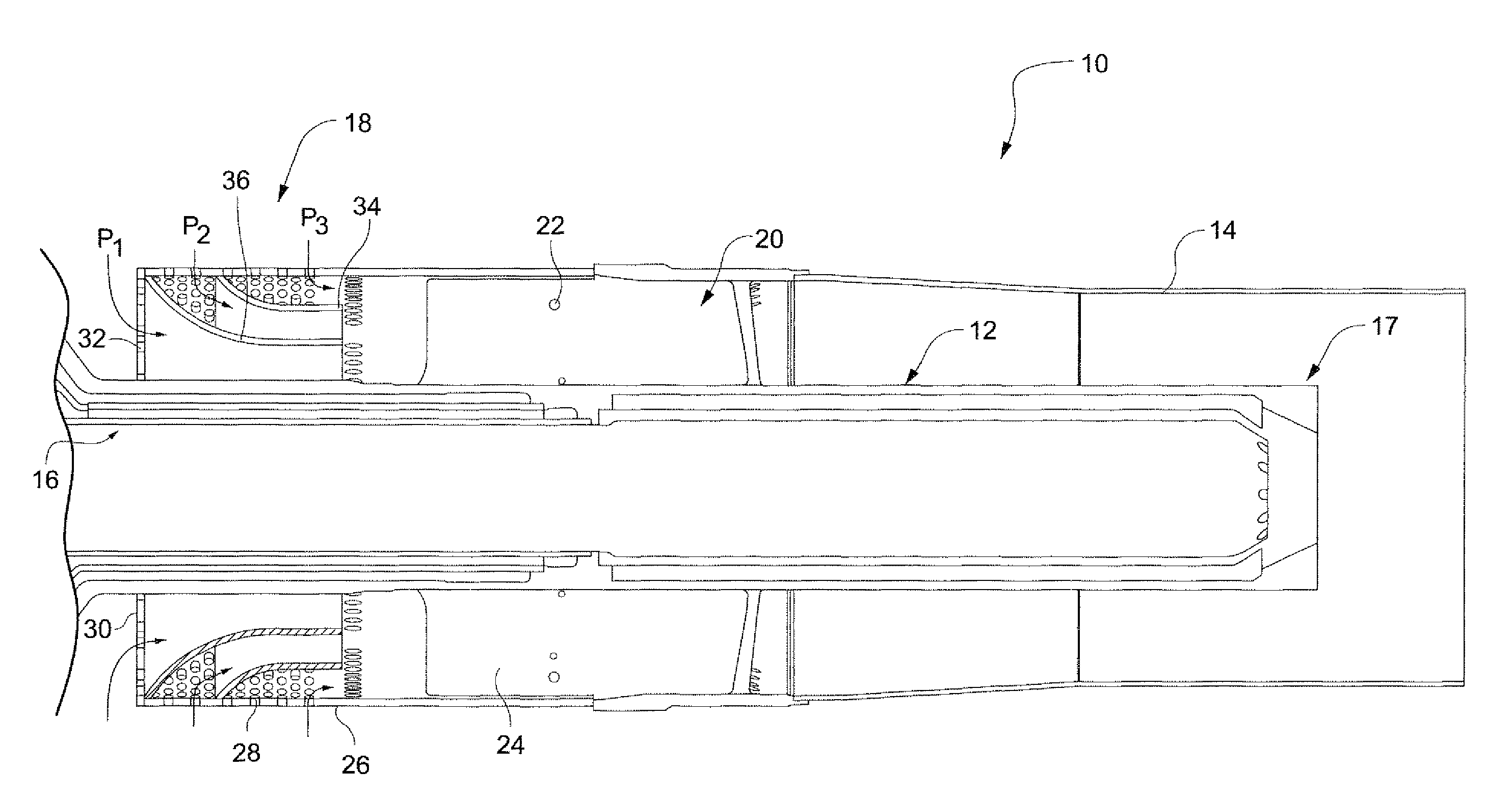
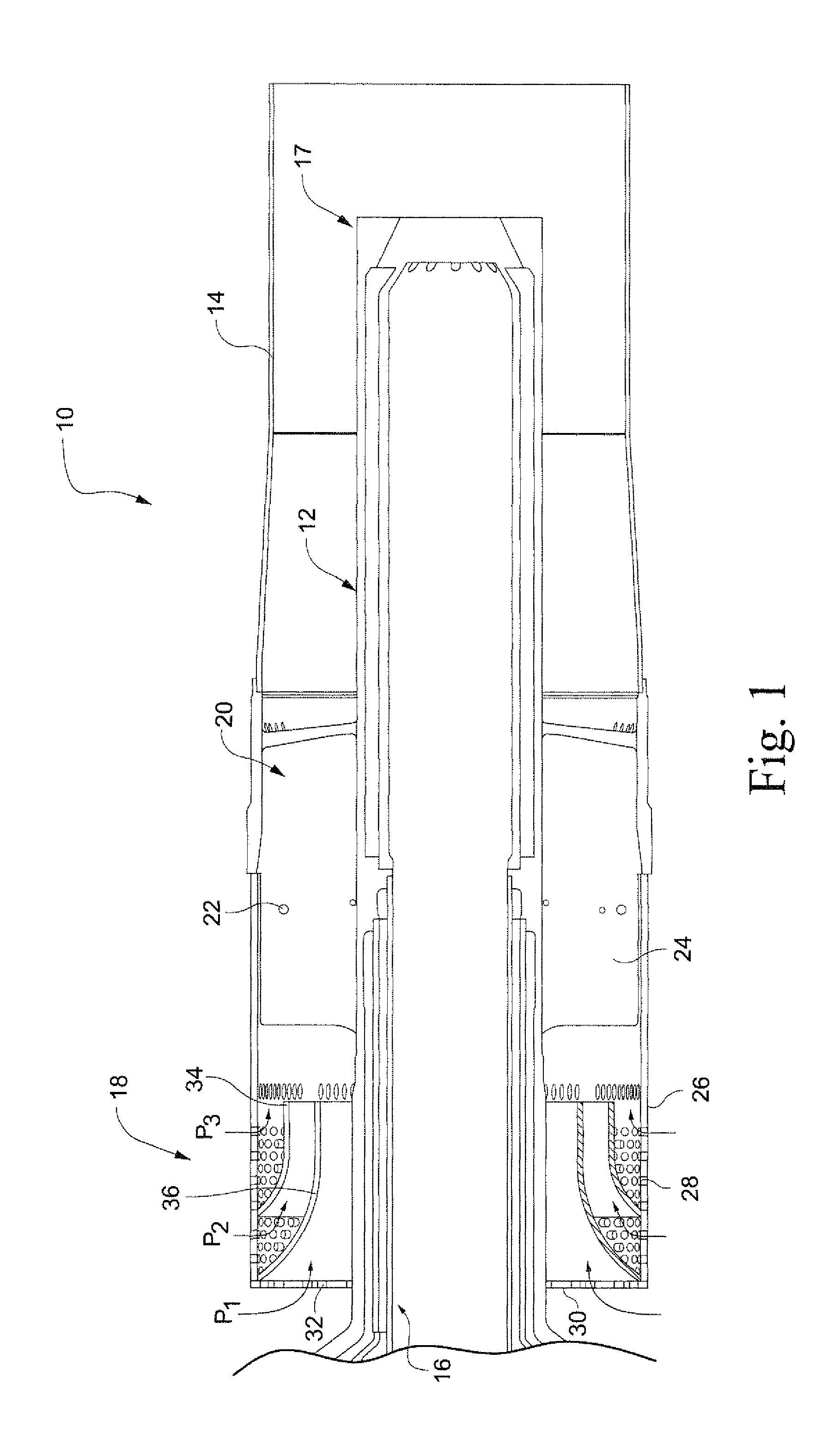
[0017]FIG. 1 illustrates a gas turbine combustor nozzle 10 including a radially inner center body 12 and a radially outer support tube 14. A mounting flange (not shown) is located at the forward end (i.e., to the left in FIG. 1) of the nozzle and facilitates mounting the nozzle to the combustor. Fuel and air are supplied to the combustion chamber through plural passages indicated generally at 16 within the center body, exiting at the center body aft or outlet end 17 (i.e., to the right in FIG. 1). An inlet flow conditioner 18 is secured to the outer nozzle support tube 14 at a location upstream of a swirler 20 where fuel is injected through apertures 22 in the hollow vanes 24 of the swirler into air that has passed through the conditioner 18. The air and fuel mix within the annulus formed by the outer support tube 14 and the center body 12 and then burn once they enter the combustion chamber in a manner well understood by those skilled in the art.

[0018]The inlet flow conditioner 18 ...


PUM

PropertyMeasurementUnit
Flow rateaaaaaaaaaa

Abstract

A nozzle center body includes a unitary, one-piece, elongated tubular member having a forward end formed with a radially outwardly extending mounting flange; an aft end formed with a plurality of radially outwardly extending swirler vanes; and, an intermediate region, located axially between the forward and aft ends, formed with an inlet flow conditioner including an annular plate provided with plural, circumferentially-spaced flow openings therein. A related method of forming the nozzle center body by casting is also disclosed.

Description

BACKGROUND OF THE INVENTION[0001]This invention relates to gas turbine combustor technology and, more specifically, to the manufacture of an inlet flow conditioner integrated with a gas turbine combustor fuel nozzle.[0002]Inlet flow conditioners are used to remove both radial and circumferential variations in air flowing into a fuel nozzle. More specifically, the inlet flow conditioner reduces the large velocity and pressure gradients entering the fuel nozzle so that the air and gas fuel will mix in a uniform and predictable manner. If the air entering the fuel nozzle has substantial circumferential and radial flow variations, achieving the required precise fuel and air ratios becomes problematic.[0003]Not all combustor fuel nozzles utilize inlet flow conditioners. Many nozzles simply use an inlet Bell mouth configuration; however, when trying to achieve a very uniform inlet air stream in a combustor configuration where the fuel nozzles are densely-packed, a more complicated inlet f...

Claims


Application Information

Patent Timeline
IPC IPC(8): B05B1/26B21D51/16
CPCF23R3/14Y10T29/49405F23R3/286
Inventor JOHNSON, THOMAS EDWARDMACMILLAN, JOHN BRANDON
Owner GENERAL ELECTRIC CO
Why Eureka
Try Eureka