
Orthotic device

a neurological rehabilitation and electrode technology, applied in the field of electromechanical enabled neurological rehabilitation devices, can solve the problems of increased tone or hypertonicity, inability to extend the wrist or fingers to grasp an object, and inability to use the cuffs when practical,

Active Publication Date: 2012-03-08
SAEBO
View PDF6 Cites 34 Cited by
  • Summary
  • Abstract
  • Description
  • Claims
  • Application Information

AI Technical Summary

Problems solved by technology

Many have some shoulder and elbow movements, but are unable to extend their wrist or fingers to grasp an object.
These cuffs are not practical when working on a digit affected by hypertonicity, as they move proximal upon closing the fingers, and then have to be repositioned after opening the fingers manually.
Unfortunately, with respect to the hand, patients that exhibit increased tone or hypertonicity are unable to effectively use electrical stimulation with or without current orthotics on the market.
Neurological patients are unable to adequately extend their fingers, specifically at the PIP and DIP joints, when electrical stimulation is applied.
Current FES prostheses do not effectively take wrist position into consideration.
Currently, there are no devices available that mechanically extend the wrist and hand while receiving electrical stimulation.
Electrode placement is an important issue for FES since the patient or their caretaker is required to set up the device each time they wish to use it.
Many devices do not offer features that reliably position the electrodes in the correct location in a timely manner.

Method used


Image

  • Orthotic device
  • Orthotic device
  • Orthotic device

Examples


second embodiment

[0063]Referring to FIG. 11B, a finger tensioner is shown having a finger cap 400 moveably coupled to a flexible longitudinal spine 434. Additionally, a plurality of support uprights 430A and 430B are rigidly coupled to flexible longitudinal spine 434 so that each upright does not move relative to the spine. Spine 434 may be formed from various suitable polymers and elastomers, or some combination thereof. When a finger is moved into flexion, uprights 430A and 430B become spaced apart as the spine flexes, while a tension cable 428 provides restoring force. Tension cable 428 may be coupled to handpiece spindle 376 (FIG. 10) similar to the previous embodiment. Loops 432 formed on each upright act as guides for tension cable 428, and also act as anchor points so that the restoring force at each knuckle can be adjusted.

third embodiment

[0064]Referring to FIG. 11C, a finger tensioner is illustrated having a finger cap 400B coupled to a plurality of longitudinal plates 436, 442 and 444. Each longitudinal plate is positioned adjacent a respective proximal, intermediate and distal phalange. Intermediate each longitudinal plate is a flexure 440 so that two adjacent flexures are positioned at each interphalangeal joint. One knuckle flexure 438 is positioned proximate the finger knuckle. Thus, as a finger is moved into flexion flexures 440 become compressed building restorative force between the adjacent flexures. In one preferred embodiment, the flexures are formed from spring steel. However, it should be understood that in other embodiments, the flexures and longitudinal plates may be formed from any suitable material.

[0065]Referring to FIG. 11D, one preferred embodiment of a thumb tensioner 310 is shown coupled to hand support section 302 by a ball and socket joint. Referring to FIG. 11E, another preferred embodiment ...


PUM


Abstract

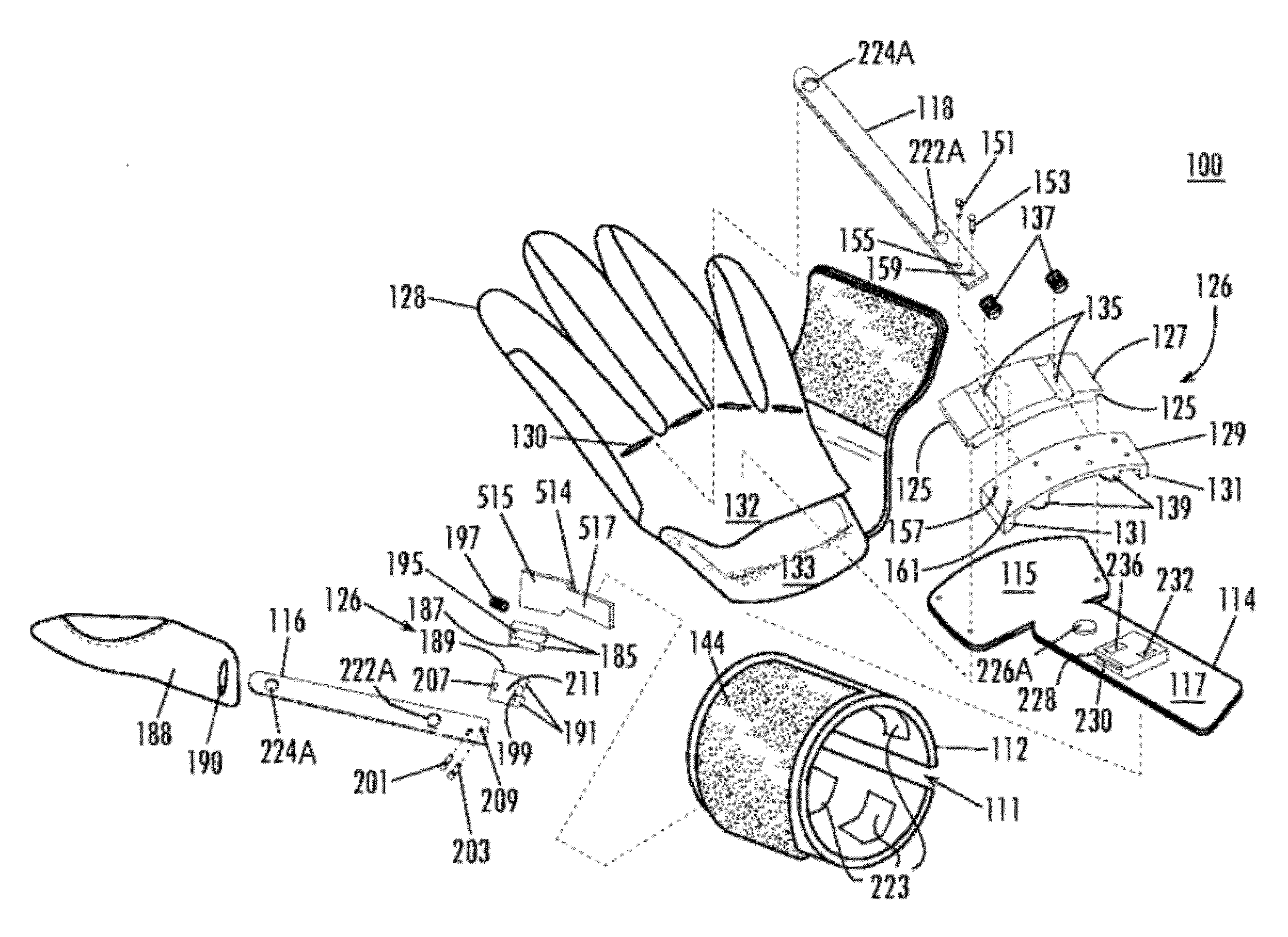
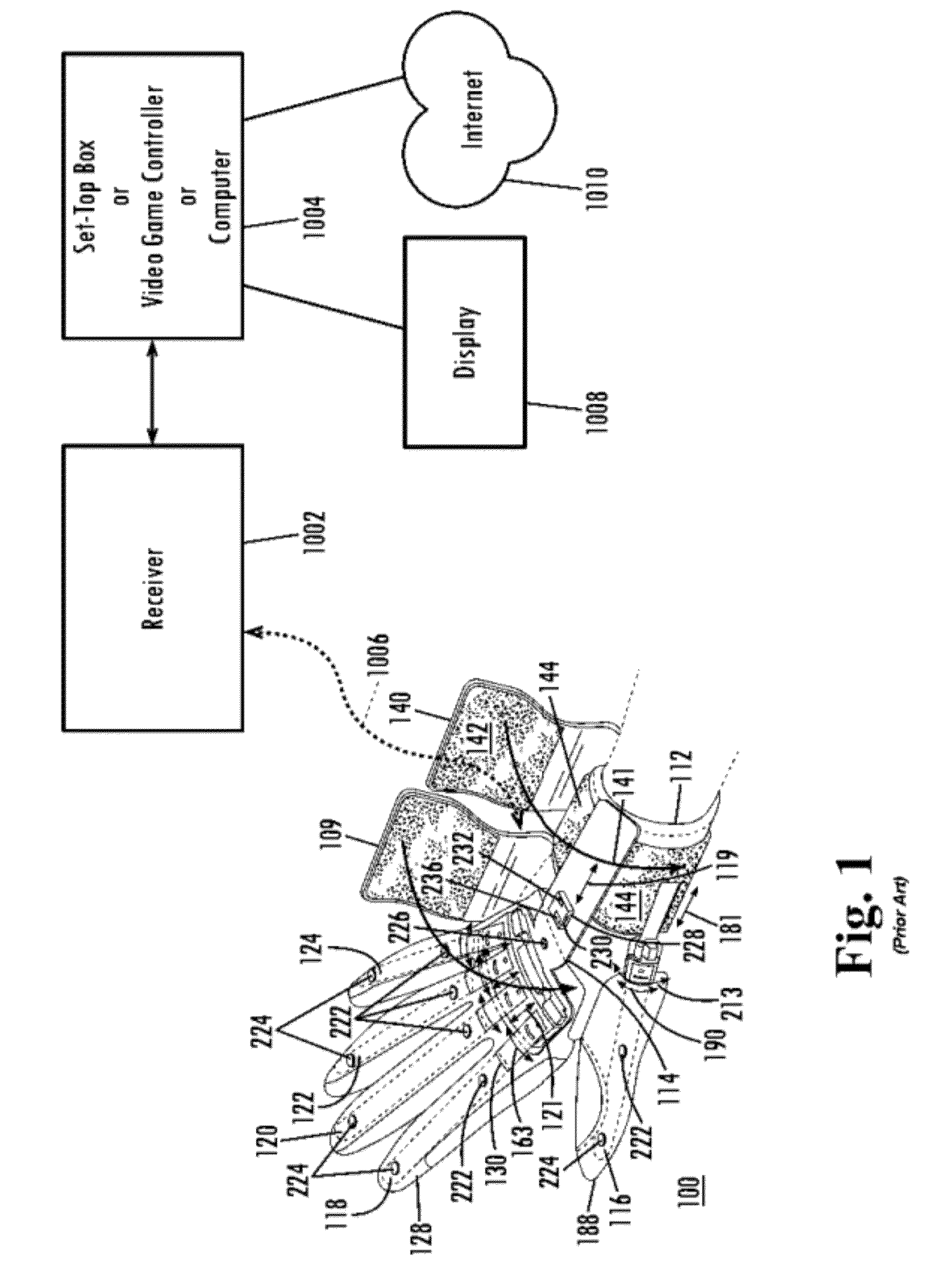
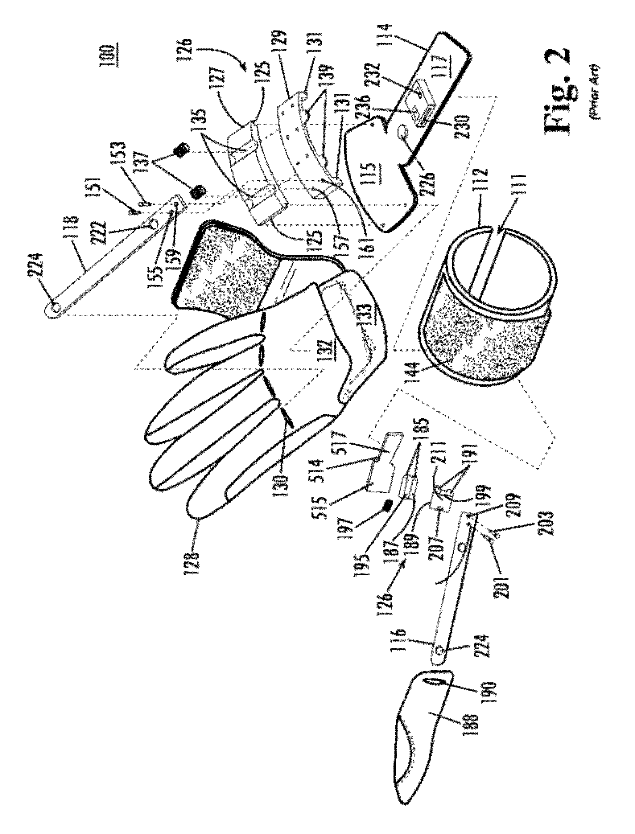
An orthotic device including a forearm support section configured to be releasably attached to a user's arm, a hand support section configured to be releasably attached to the user's hand, and an adjustable joint coupled to the forearm support section and the hand support section. At least one electromyography sensor is coupled to the forearm support section and positioned to sense activity of muscles in the user's arm, at least one electrode is coupled to the forearm support section and configured to provide electrical stimulation to muscles in the user's arm, and a controller is operatively coupled to the at least one electrode, the controller being configured to deliver electrical stimulation to the at least one electrode.

Description

CLAIM OF PRIORITY[0001]This application claims priority to U.S. Provisional Patent Application No. 61 / 350,358 filed Jun. 1, 2010, the entire disclosure of which is hereby incorporated by reference herein.FIELD OF THE INVENTION[0002]The present invention relates to the field of neurological rehabilitation device constructions in general, and more particularly to an electronic enabled neurological rehabilitation device.BACKGROUND OF THE INVENTION[0003]A dynamic wrist-hand-finger orthosis or splint is generally used for the positioning of an impaired, injured, or disabled wrist, hand, and fingers. Splints come in a variety of designs: static, static progressive, and dynamic that can be low profile or high profile. Most prior art splints are neurological in nature that either holds the hand in a static functional position, or uses a slight dynamic force to position the fingers.[0004]Many people suffering a neurological injury from stroke, cerebral palsy, brain injury, etc., have upper e...

Claims


Application Information

Patent Timeline
Patent Type & Authority Applications(United States)
IPC IPC(8): A61F5/00
CPCA61F5/013A61N1/36014A61N1/36003A61F2/72A61N1/36031
Inventor HOFFMAN, HENRY B.MACON, G. PETERKIRKLAND, DAVIDSPENCER, MATTHEWKOH, LINDAPOE, DOUGLAS
Owner SAEBO
Learn More