
Method and apparatus for determining a convergence angle of a stereo camera

a convergence angle and camera technology, applied in the field of stereo cameras, can solve the problems of large size and volume of conventional stereo cameras, high manufacturing costs,

Inactive Publication Date: 2012-03-15
SAMSUNG ELECTRONICS CO LTD
View PDF10 Cites 16 Cited by
  • Summary
  • Abstract
  • Description
  • Claims
  • Application Information

AI Technical Summary

Problems solved by technology

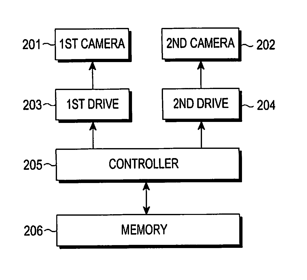
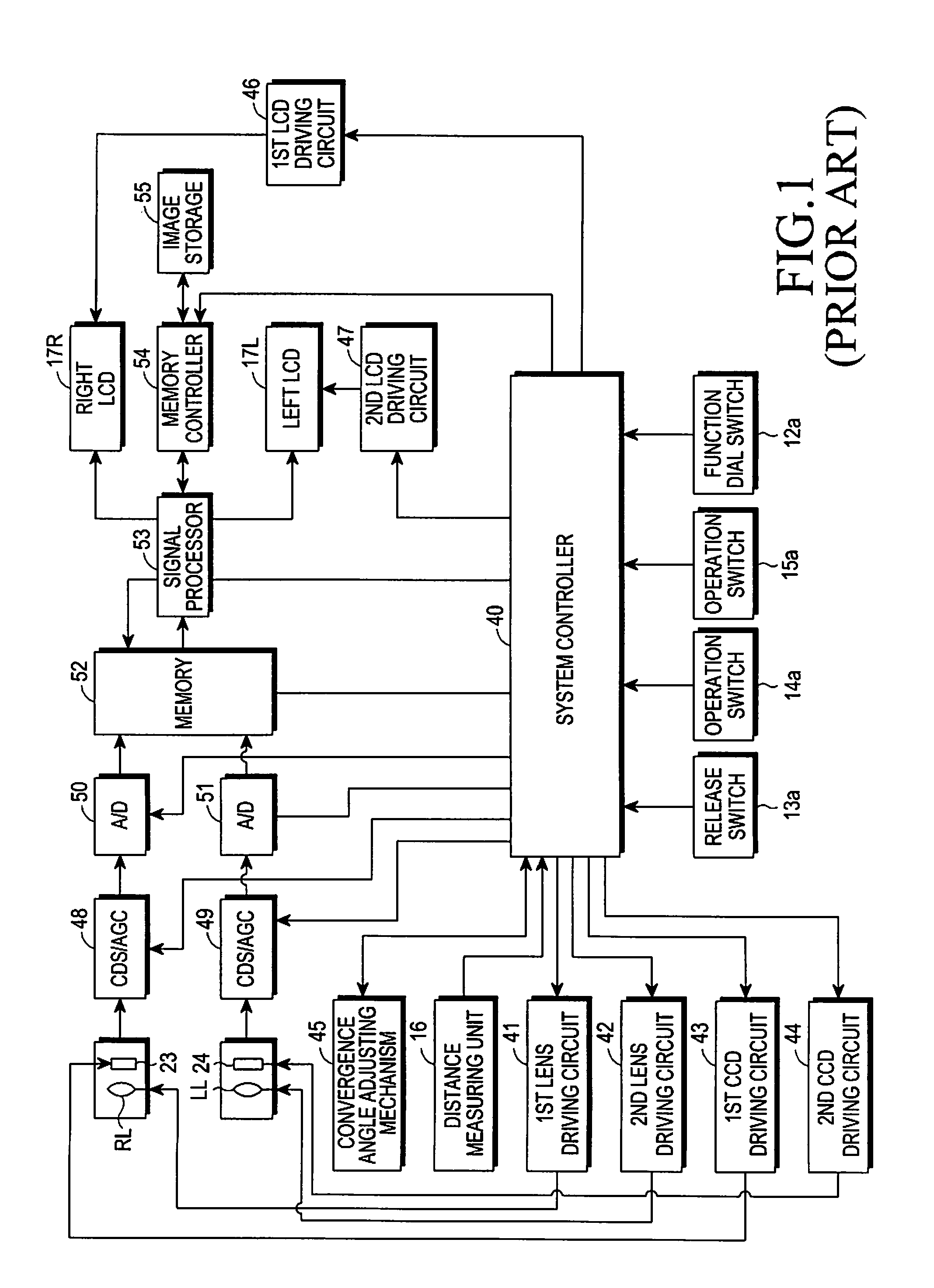
However, because the distance measuring unit 16 is an additional physical component, the size and volume of the conventional stereo camera are large and its manufacturing expense is high.

Method used


Image

  • Method and apparatus for determining a convergence angle of a stereo camera
  • Method and apparatus for determining a convergence angle of a stereo camera
  • Method and apparatus for determining a convergence angle of a stereo camera

Examples


Embodiment Construction

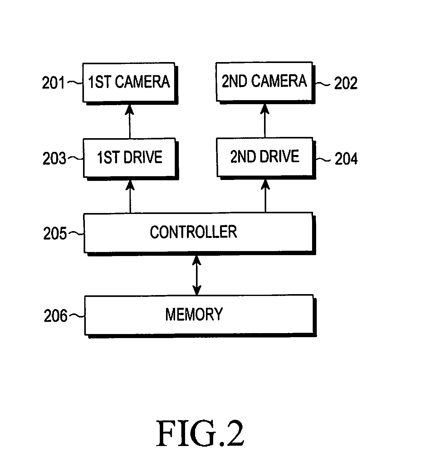
[0023]Hereinafter, various embodiments of the present invention will be described with reference to the accompanying drawings. In the following description, same elements will be designated by same reference numerals although they are shown in different drawings. Further, various specific definitions found in the following description are provided only to help general understanding of the present invention, and it is apparent to those skilled in the art that the present invention can be implemented without such definitions. Further, in the following description of the present invention, a detailed description of known functions and configurations incorporated herein will be omitted to avoid obscuring the subject matter of the present invention.

[0024]In accordance with an embodiment of the present invention, a method is provided for determining a convergence angle of a stereo camera. For this purpose, the method may include setting interest regions in each image photographed by the s...


PUM


Abstract

An apparatus and method of determining a convergence angle of a stereo camera. The method includes setting interest regions by first and second cameras, respectively, the interest regions having a same size and being symmetric to each other; photographing images by the first and second cameras while varying a convergence angle of the stereo camera by a predetermined degree for each photographed image of the first and second cameras, respectively; analyzing image histograms of the interest regions for each of the first and second cameras; and setting an optimum convergence angle.

Description

PRIORITY[0001]This application claims priority under 35 U.S.C. §119(a) to an application filed in the Korean Industrial Property Office on Sep. 14, 2010 and assigned Serial No. 10-2010-0090144, the content of which is hereby incorporated by reference.BACKGROUND OF THE INVENTION[0002]1. Field of the Invention[0003]The present invention relates generally to a stereo camera for acquisition of a three-dimensional (3D) image, and more particularly, to a method and an apparatus for determining a convergence angle of a subject photographed by the stereo camera.[0004]2. Description of the Related Art[0005]A stereoscopic 3D image refers to an image capable of expressing a 3D effect of an object, in addition to depth and space formation information, which cannot be achieved through a 2D image. Basically, a 3D effect is obtained by a difference between right and left images as seen by both eyes, and a stereoscopic 3D image is recognized through a synthesizing process by the brain. In order to ...

Claims


Application Information

Patent Timeline
Patent Type & Authority Applications(United States)
IPC IPC(8): H04N13/02
CPCH04N13/0239H04N2013/0081H04N13/0246H04N13/246H04N13/239H04N13/128H04N13/122
Inventor SEO, JA-WONLEE, HAE-SUNLEE, JONG-HYUBYIM, SUNG-JUN
Owner SAMSUNG ELECTRONICS CO LTD
Learn More