
Method and Device for Determining a Calibrating Parameter of a Stereo Camera

a calibration parameter and camera technology, applied in the direction of image analysis, image enhancement, instruments, etc., can solve the problems of inability to ultra-precisely calibrate the camera system, only possible position determination of image contents with the aid of the camera, and inability to achieve ultra-precise calibration. , to achieve the effect of stable over an extended period of time and considerable inaccuracy of measurement results

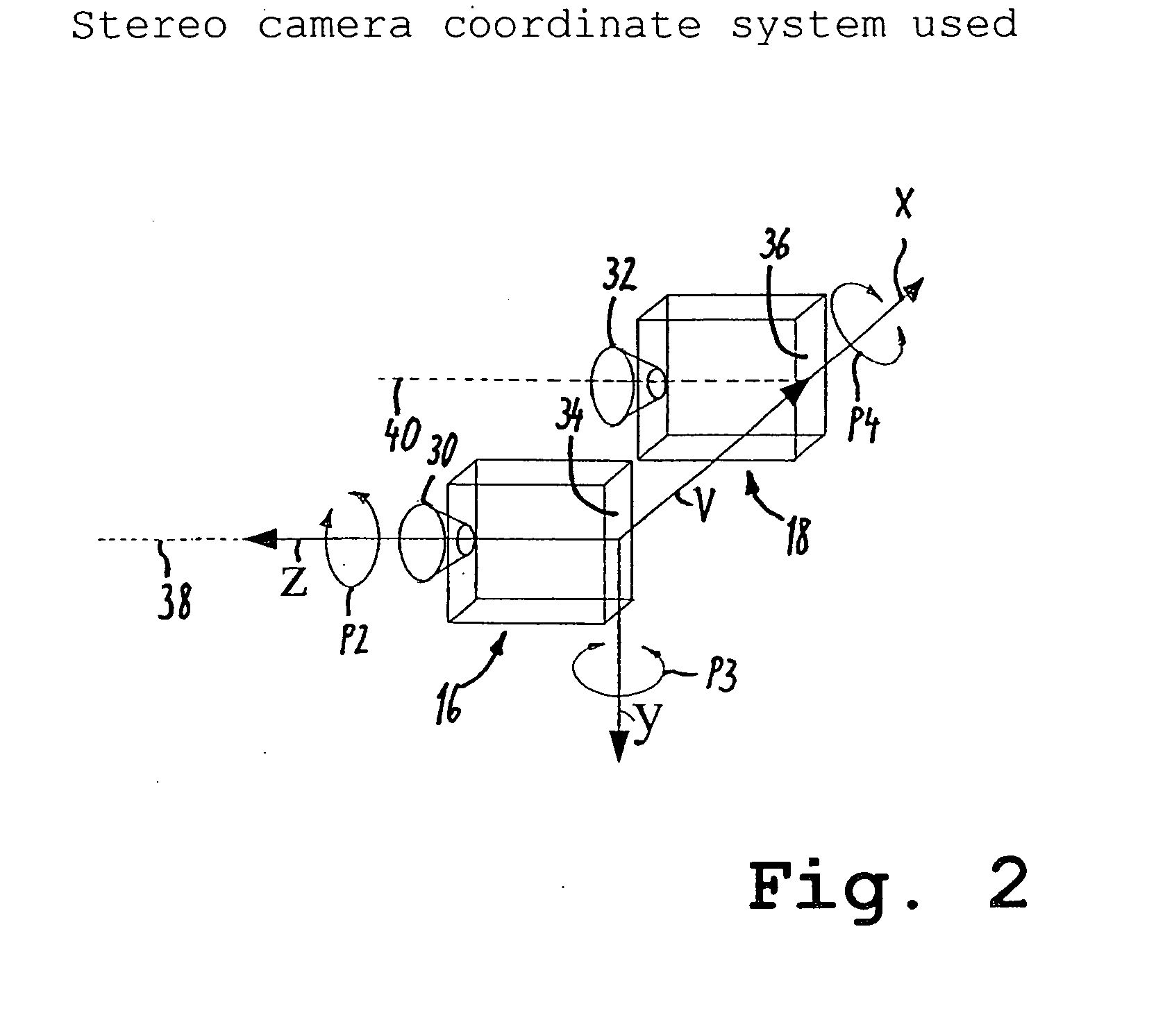
Active Publication Date: 2008-06-19
CARIAD SE
View PDF2 Cites 75 Cited by
  • Summary
  • Abstract
  • Description
  • Claims
  • Application Information

AI Technical Summary

Benefits of technology

[0003]Known stereo camera systems comprise two single-image cameras, each of which preferably comprise a CCD sensor and a fixed focal length lens system or, alternatively, a CMOS image sensor and such a lens system. Preferably, the single-image cameras simultaneously take one image each. These images are referred to as an image pair. With the aid of the images taken, a direct distance measurement of objects visible in both images can be made. For determining the distance, it is important to precisely know, in addition to the camera parameters, also the orientation of the optical axes of the single-image cameras with respect to one another. A stable construction can for example be chosen, by means of which the two cameras only slightly change their position to one another under intended operating conditions. As a result thereof, stability over an extended period of time is achieved for a calibrated system. In addition to the relatively complex structure, which also occupies a considerable amount of space, considerable inaccuracy of the measurement result can occur during distance measurement as a result of changes in position of the cameras with respect to one another despite the stable construction. This requires a range limit for the distance measurement in order to obtain measurement results within a reasonable tolerance. Only by means of a stable construction and a limitation of the measurement accuracy and the range, can distance measurements usefully be made over a longer period of time with such a stereo camera system without complex calibration services having to be performed in the meantime.

Problems solved by technology

In addition to the relatively complex structure, which also occupies a considerable amount of space, considerable inaccuracy of the measurement result can occur during distance measurement as a result of changes in position of the cameras with respect to one another despite the stable construction.
However, given this method the position determination of the image contents with the aid of the cameras is only possible with an accuracy that depends on the camera resolution.
Thus, an ultra-precise calibration of the camera system is not possible with the aid of such a known method.

Method used


Image

  • Method and Device for Determining a Calibrating Parameter of a Stereo Camera
  • Method and Device for Determining a Calibrating Parameter of a Stereo Camera
  • Method and Device for Determining a Calibrating Parameter of a Stereo Camera

Examples


Embodiment Construction

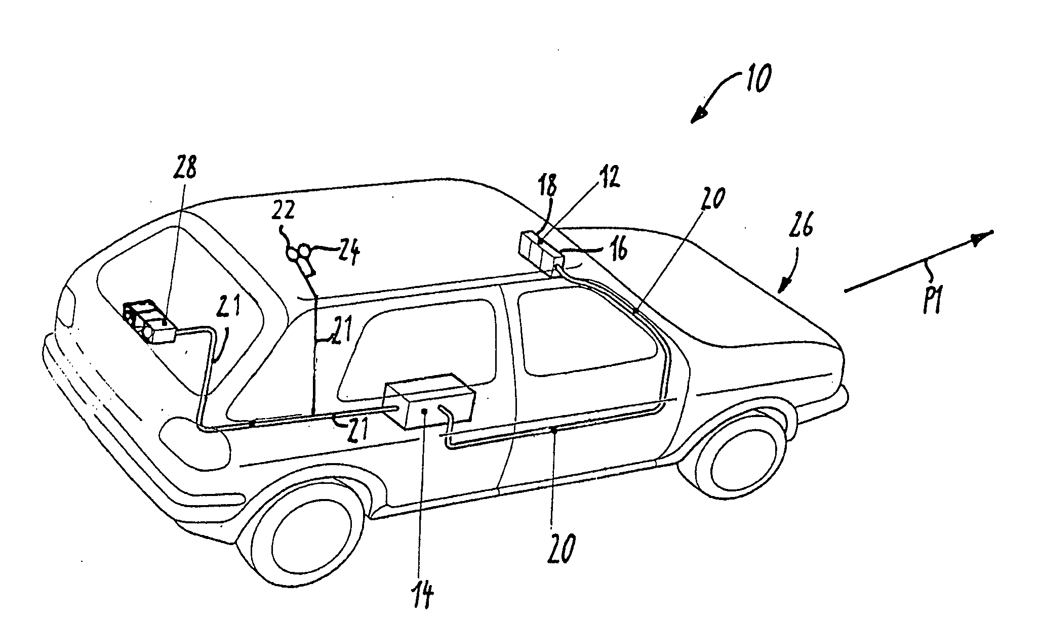
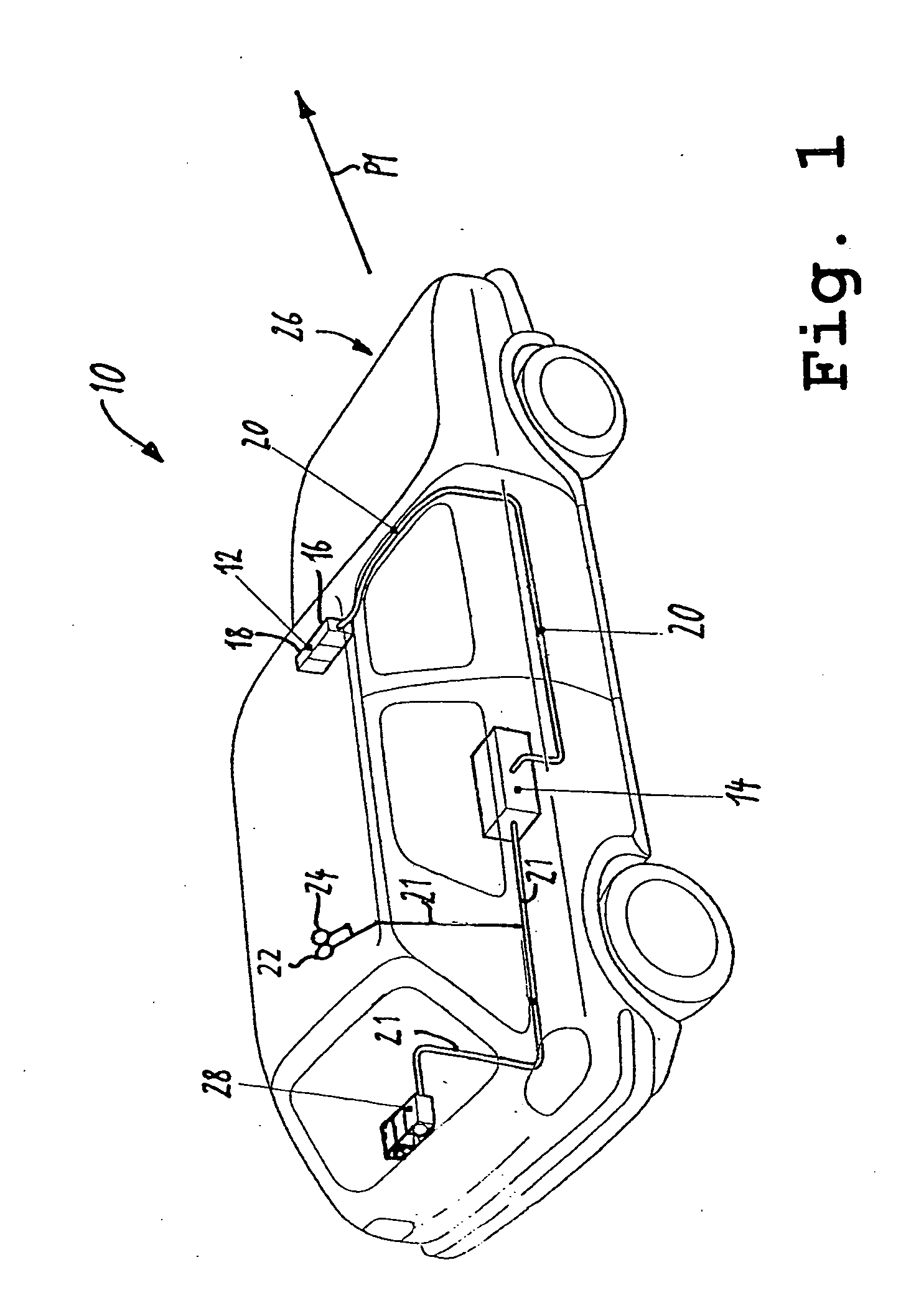
[0051]In FIG. 1, an automobile 10 is illustrated in which a stereo camera system comprising a stereo camera 12 and a control and evaluation unit 14 is provided. The stereo camera 12 comprises two single-image cameras 16, 18, which are arranged next to one another at a distance substantially transversely to the direction of travel P1. The optical axes of the cameras 16, 18 are oriented such that with the aid of the cameras 16, 18 an area in front of the automobile 10 is captured. The optical axes of the cameras 16, 18 preferably have a yaw angle with respect to one another.

[0052]In other embodiments, the two optical axes of the cameras 16, 18 can also be oriented exactly parallel with respect to one another. The cameras 16, 18 each simultaneously record a single image of more or less the same surrounding in front of the automobile 10, the cameras 16, 18 preferably having an optoelectric converter, in particular a CCD or a CMOS image sensor, and a fixed focal length lens system. The s...


PUM


Abstract

The invention relates to a method and a device for determining an object property of an object with the aid of images that have been recorded with the aid of a camera. Further, the invention relates to a method for determining a calibration parameter for a stereo camera. For determining the object property of an object, the object is defined in a first image recorded with the aid of the camera. Further, the brightness of a defined object is determined. Each time after a preset time interval, a further image is recorded with the aid of the camera. The object is defined in each of the further images and each time, the brightness of the defined object of each image is determined. Dependent on the brightness curve, an object property is assigned to the object.

Description

FIELD OF THE INVENTION[0001]The invention relates to a method and a device for determining a calibration parameter of a stereo camera. With the aid of the stereo camera, object images of an object are each time recorded at least two times one after the other at an interval, and each time the distance between the stereo camera and the object is determined.[0002]Further, the invention relates to a method and a device for determining an object property of an object with the aid of images which have been recorded with the aid of a camera as well as to a computer software and a data carrier carrying this computer software.SUMMARY OF THE INVENTION[0003]Known stereo camera systems comprise two single-image cameras, each of which preferably comprise a CCD sensor and a fixed focal length lens system or, alternatively, a CMOS image sensor and such a lens system. Preferably, the single-image cameras simultaneously take one image each. These images are referred to as an image pair. With the aid...

Claims


Application Information

Patent Timeline
Patent Type & Authority Applications(United States)
IPC IPC(8): G06K9/00H04N13/239
CPCG06T7/002H04N13/0239H04N13/0246G06T2207/10012H04N2013/0085G06T7/85H04N13/239H04N13/246G06V20/584
Inventor HOFFMANN, INGO
Owner CARIAD SE
Learn More