Method and apparatus for detecting obstacles

a technology of obstacles and methods, applied in the field of vision systems, can solve the problems of inability to model the earth as a simple plane, general inaccurateness, and unnecessary evasion by the vehicle, and achieve the effect of accurately making decisions and easy traversing

Inactive Publication Date: 2005-01-20
SARNOFF CORP
View PDF9 Cites 77 Cited by
  • Summary
  • Abstract
  • Description
  • Claims
  • Application Information

AI Technical Summary

Benefits of technology

The invention provides a method and apparatus for detecting obstacles in non-uniform environments, e.g., an off-road terrain application. The apparatus uses a stereo camera and specific image-processing techniques to enable the vehicle's vision system to identify drivable terrain in front of the vehicle. The method uses the concept of a non-drivable residual (NDR), where the NDR is zero for all terrain that can be easily traversed by the vehicle and is greater than zero for terrain that may not be traversable by the vehicle. The method utilizes a depth map having a point cloud that represents the de

Problems solved by technology

In “off-road” applications, where the ground upon which the vehicle is to traverse is non-planar, the terrain cannot be modeled as a simple plane.
However, such models are gen

Method used


Image

  • Method and apparatus for detecting obstacles
  • Method and apparatus for detecting obstacles
  • Method and apparatus for detecting obstacles

Examples


Embodiment Construction

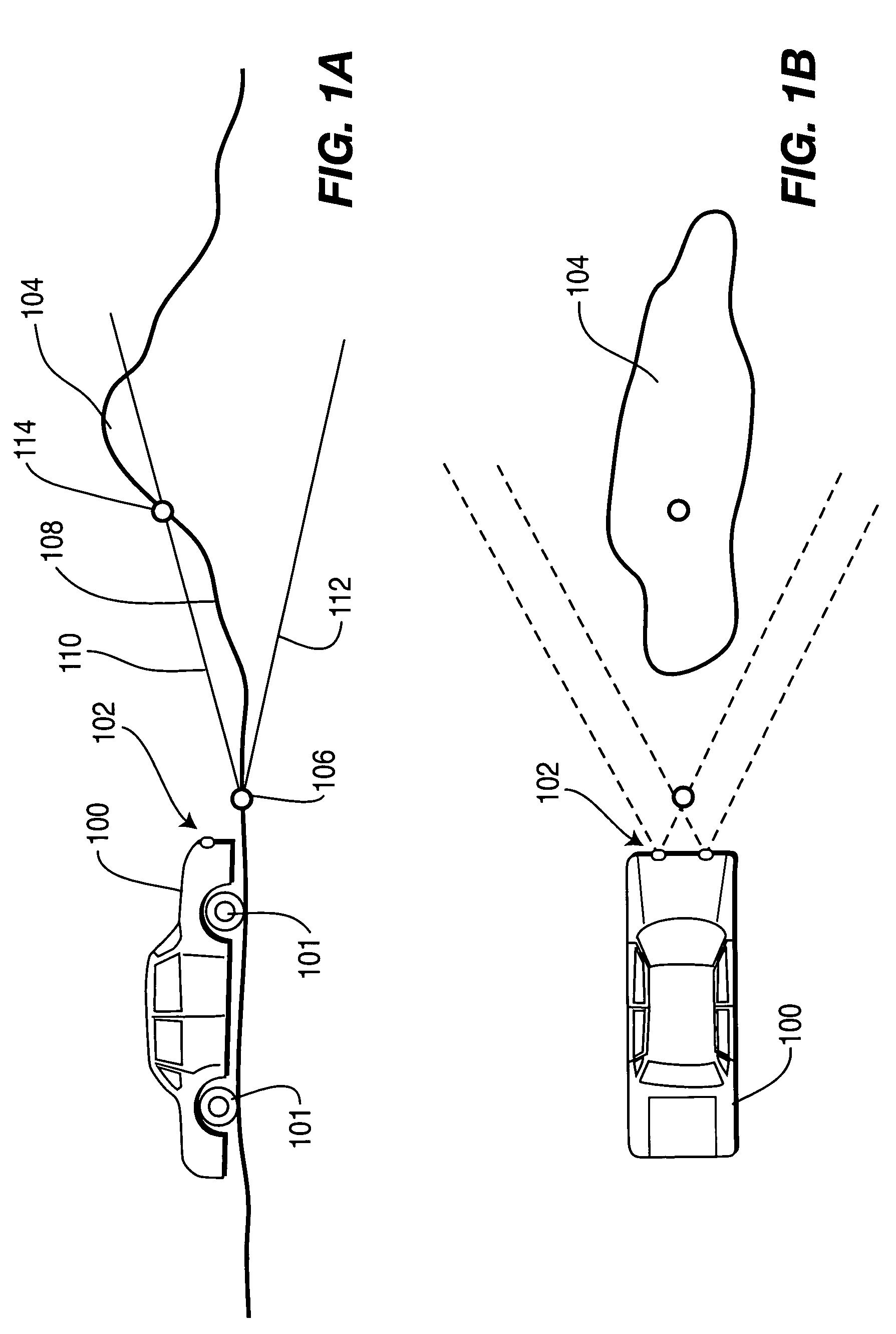
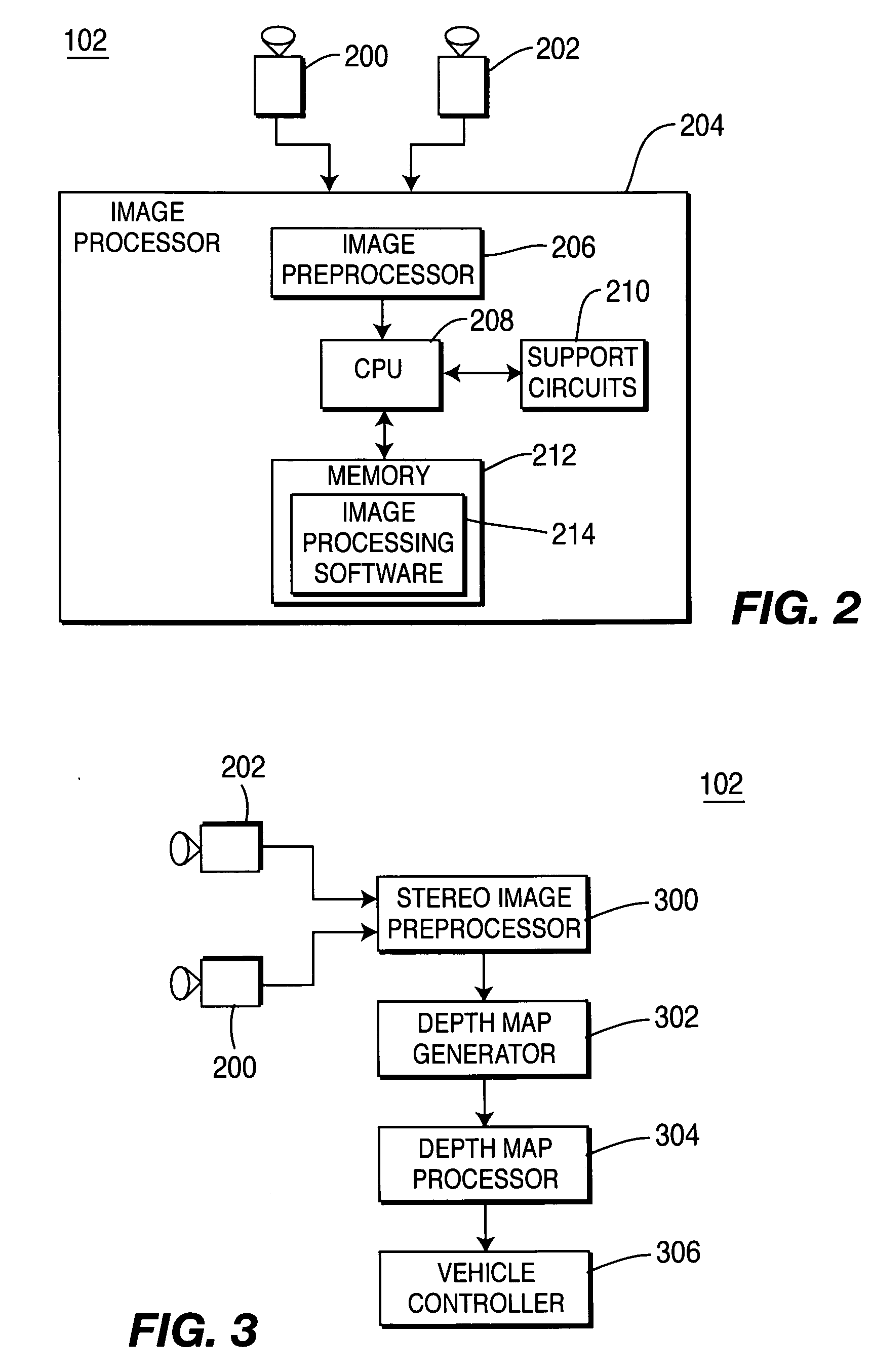
FIG. 1A depicts a side view of a vehicle 100 having a movement system 101 traversing off-road terrain and FIG. 1B depicts a top view of the terrain in FIG. 1A. The vehicle 100 contains a stereo imaging system 102 having at least a pair of sensors or cameras mounted to the front of the vehicle. In one illustrative embodiment, the vision system 102 is capable of processing video at a rate of ten frames per second or faster in real time and produces an obstacle map that has a resolution that is fine enough to identify a pathway that is a little wider than the vehicle itself. The vehicle may be an unmanned ground vehicle (UGV) that uses the obstacle detection method of the present invention to enable the vehicle's control system to direct the vehicle around detected obstacles. Alternatively, the invention could also be used as an obstacle avoidance warning system for a manned vehicle or for a system that detects the slope of terrain to enable a driver to understand whether the slope is ...


PUM


Abstract

A method and apparatus for detecting obstacles in off-road applications. A stereo camera and specific image-processing techniques enable a vehicle's vision system to identify drivable terrain in front of the vehicle. The method uses non-drivable residuals (NDR), where the NDR is zero for all terrain that can be easily traversed by the vehicle and greater than zero for terrain that may not be traversable by the vehicle. The method utilizes a depth map having a point cloud that represents the depth to objects within the field of view of the stereo cameras. The depth map is tiled such that the point cloud data is represented by an average (smoothed) value. The method scans pixels in the smoothed depth map to find sequences of “good” points that are connected by line segments having an acceptable slope. Points that lie outside of the acceptable slope range will have an NDR that is greater than zero. The vehicle control system can use the NDRs to accurately make decisions as to the trajectory of the vehicle.

Description

BACKGROUND OF THE INVENTION 1. Field of the Invention The invention relates to vision systems and, more particularly, the present invention relates to a method and apparatus for detecting obstacles using a vehicular-based vision system. 2. Description of the Background Art Vehicular vision systems generally comprise a camera (or other sensor) mounted to a vehicle. An image processor processes the imagery from the camera to identify obstacles that may impede the movement of the vehicle. To identify obstacles, a plane is used to model the roadway in front of the vehicle and the image processor renders obstacles as point clouds that extend out of the plane of the roadway. By using such a planar model, the processing of imagery from “on-road” applications of vehicular vision systems is rather simple. The image-processing system must recognize when the point cloud is extending from the roadway plane and deem the point cloud simply to be an obstacle to be avoided. In “off-road” appli...

Claims


Application Information

Patent Timeline
IPC IPC(8): G06KG08G1/16
CPCG08G1/163G06V20/64G06V20/588G06V10/462
Inventor FIELDS, JOHN RICHARDSOUTHALL, JOHN BENJAMIN
Owner SARNOFF CORP
Why Eureka
Try Eureka