Caster wheel lift and brake assembly

a technology for caster wheels and assembly, which is applied to vehicle components, castors, multi-purpose tools, etc., can solve the problems of difficult to negotiate over even small obstacles, complicated situation, and more difficult use of above suspension systems, so as to facilitate the traversal of obstacles

Active Publication Date: 2013-09-24
WAGGENER HERBERT A
View PDF60 Cites 9 Cited by
  • Summary
  • Abstract
  • Description
  • Claims
  • Application Information

AI Technical Summary

Benefits of technology

[0011]The invention is applicable to caster wheels and incorporates a variable pivot and a caster rotational brake. In a preferred embodiment of the invention, the caster wheel assembly having a caster-axis brake and a barrier-traversing member comprises a caster support body having a vertical caster shaft with a shaft axis therein. The vertical caster shaft is pivotally engaged within a caster shaft housing having a stator surface adjacent the caster support body. At least one caster wheel is mounted on a horizontal axle in the caster support body opposite the caster shaft, with the horizontal axle offset from the vertical axis of the caster shaft. At least one barrier-traversing member is biasedly fastened to the caster support body. The barrier-traversing member includes a barrier contact surface adjacent to and aligned in parallel with said caster wheel. The barrier contact surface extends opposite said caster wheel and preferably beyond the vertical axis of the caster shaft. A braking surface member is attached to the barrier contact member opposite the barrier contact surface and adjacent the stator surface of the caster shaft housing. In operation, the moving caster wheel assembly first contacts an obstacle with the barrier contact surface of the barrier-traversing member. The encountered obstacle begins to elevate the barrier-traversing member with little force and easily brings the attached braking surface member into contact with the stator surface of the caster support body, thereby maintaining the orientation of the caster support body and said caster wheel thereof. Then, further forward movement of the directionally restrained caster wheel assembly allows the barrier-traversing member to elevate said caster wheel, transfer the load to the caster wheel, allow the barrier-traversing member to return to it's starting position, and the caster wheel to more easily traverse the obstacle.
[0012]In a first embodiment of the invention, the caster wheel assembly includes at least one barrier-traversing member, comprising a planar section termed a “Wheelcrutch,” mounted to the caster support body holding the at least one caster wheel. The barrier contact surface of said planar section may deviate from circularity to overcome a greater range of barrier heights. A further feature includes an adjustable-length barrier-traversing member and an adjustable rim portion on the barrier-traversing member, thus permitting operational optimization for the obstacles expected to be experienced.

Problems solved by technology

Many users of manually powered wheelchairs find it easy to maneuver on flat, hard floors, but have difficulty negotiating over even small obstacles.
However, if an obstacle such as a door threshold or elevation change in an otherwise smooth, level surface is encountered, the situation is more complicated, and the above suspension system is more difficult to use.
However, the smaller the castor wheel diameter, the greater the difficulty in overcoming even small obstacles.
(2) If an obstacle is disposed such that the caster encounters the obstacle in an oblique or off-center manner, the caster wheel may be forced to turn in an undesired direction, making navigation very difficult or impossible.
Wheelaids are not intended to allow wheelchairs to negotiate curbs, stairs, or other similar obstacles.
Wheelaids can also be applied to powered wheelchairs, potentially resulting in lower motor torque requirements, lighter designs, or longer cruising ranges.

Method used


Image

  • Caster wheel lift and brake assembly
  • Caster wheel lift and brake assembly
  • Caster wheel lift and brake assembly

Examples


Embodiment Construction

Nomenclature

[0022]

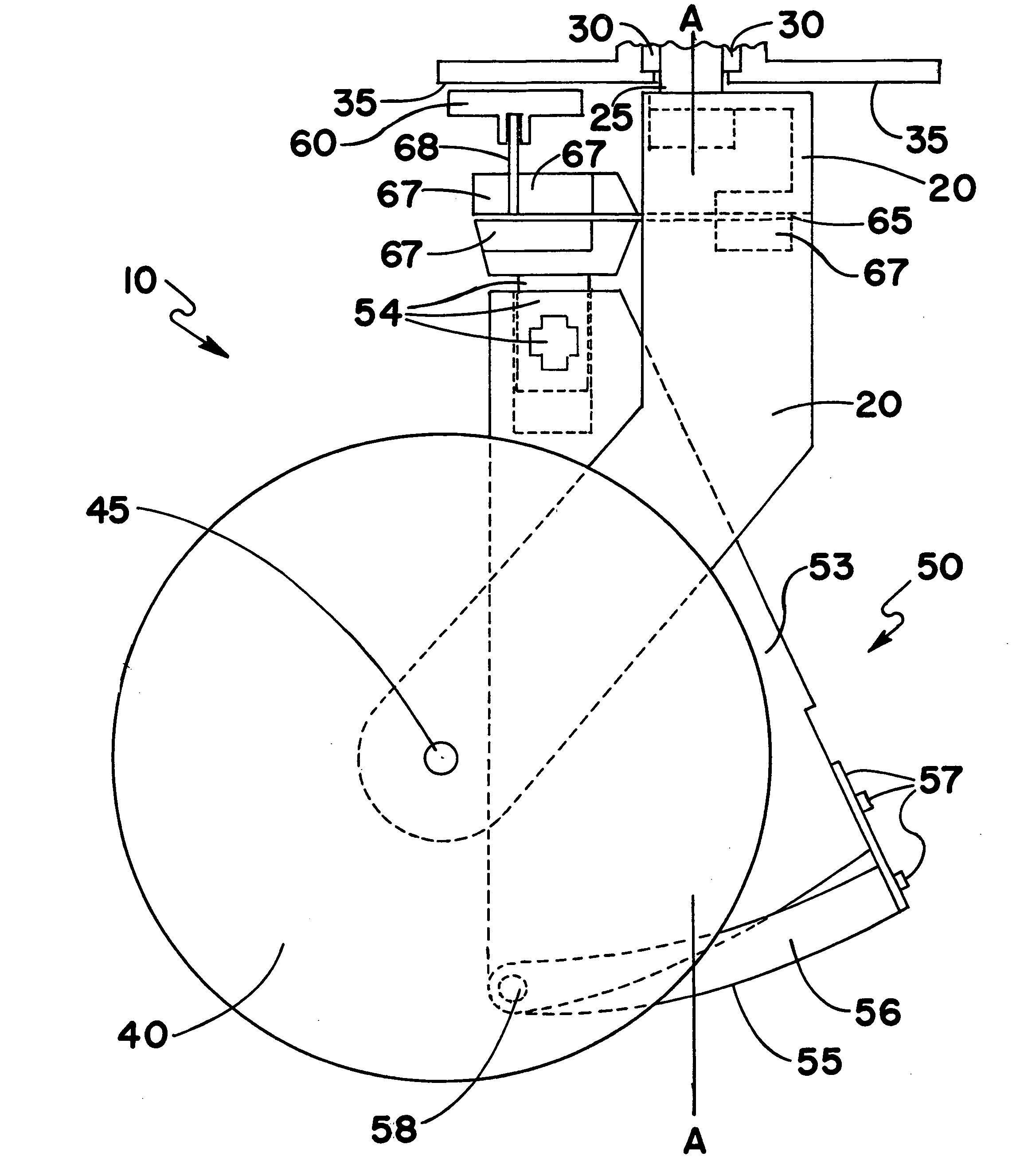
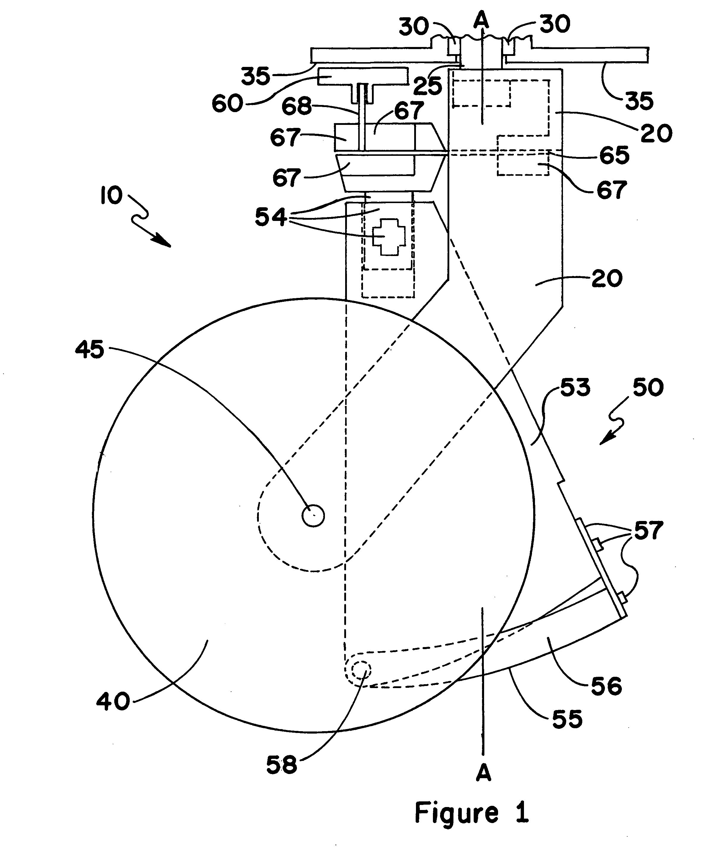
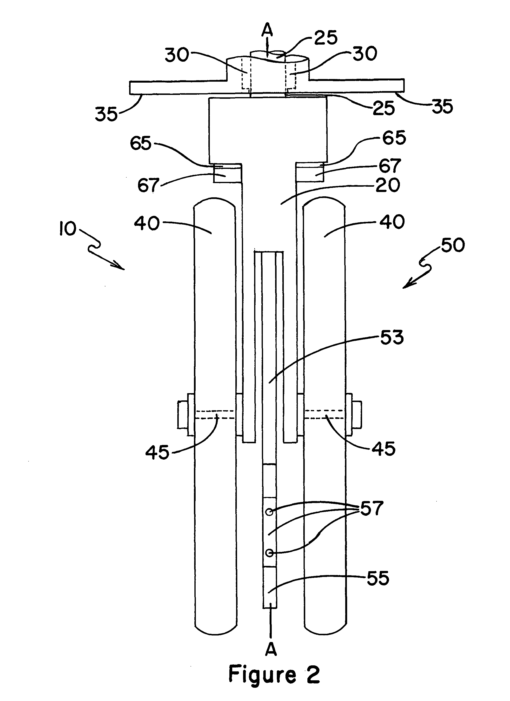
10Caster Wheel Assembly20Caster Support Body25Caster Shaft30Caster Shaft Housing35Stator Surface40Caster Wheel45Axle of Caster Wheel50Barrier-traversing Member53Rigid Planar Body54Dovetail Extension Elements and Locking Knob55Barrier Contact Surface56Adjustable Rim Portion of Barrier-traversing Member57Adjustment Strap and Retaining Bolts58Pivot Pin of Adjustable Rim60Braking Surface Member65First Flexure Member67Flexure Clamp Member68Second Flexure Member69Rigid Connector Plate Member70Linear Actuator Element75Raised Wheel Member of Actuator Element80Axle of Raised Wheel Member85Wheel Ramp Support Member90Wheel Ramp Belt Member100Compound Hinge Assembly110Body of Compound Hinge115Anchor Blocks120Bearing Shafts125Nuts of Bearing Shafts130Delrin WashersA-AVertical Axis of Caster Shaft

Construction

[0023]The invention is a caster wheel assembly having an vertical axis brake and barrier-traversing member comprising a caster support body having a caster shaft with a vert...


PUM


Abstract

A caster wheel assembly includes a vertical axis brake and barrier-traversing member. The caster shaft housing contains a stator surface adjacent the caster wheel assembly. The barrier-traversing member with barrier contact surface is biasedly fastened to the caster wheel assembly. A braking surface member is attached to the barrier-traversing member opposite the barrier contact surface and adjacent the stator surface. In operation, the moving caster wheel assembly first contacts an obstacle with the barrier contact surface of the barrier-traversing member. The encountered obstacle elevates the barrier-traversing member and attached braking surface member into contact with the stator surface of the caster shaft housing, thereby restraining rotation of the caster wheel assembly. Then, further forward movement of the rotation-restrained caster wheel assembly allows the barrier-traversing member to elevate the caster wheel, transfer load to the caster wheel, and thereby more easily traverse the obstacle.

Description

CROSS-REFERENCE TO RELATED APPLICATIONS, IF ANY[0001]This application claims the benefit under 35 U.S.C. §119 (e) of co-pending provisional application Ser. No. 61 / 657,065, filed 8 Jun. 2011. Application Ser. No. 61 / 657,065 is hereby incorporated by reference.STATEMENT REGARDING FEDERALLY SPONSORED RESEARCH OR DEVELOPMENT[0002]Not applicable.REFERENCE TO A MICROFICHE APPENDIX, IF ANY[0003]Not applicable.BACKGROUND OF THE INVENTION[0004]1. Field of the Invention[0005]The present invention relates to caster wheels and, more particularly, to a brake for caster wheels and, most particularly, to a wheel lift and brake assembly for caster wheels. The description herein is focused on application to wheelchairs, but the invention is applicable to shopping carts, material transport containers, health or other disability-related appliances, and other applications utilizing caster wheels to improve maneuverability.[0006]2. Background Information[0007]Wheel chairs are widely used to contribute ...

Claims


Application Information

Patent Timeline
Patent Type & Authority Patents(United States)
IPC IPC(8): B60B33/00
CPCB60B33/006B60B33/02B60B33/0049B60B33/0057Y10T16/195B60B2200/22Y10T16/218
Inventor WAGGENER, HERBERT A.
Owner WAGGENER HERBERT A
Why Eureka
Try Eureka