
Sensor-equipped display apparatus and electronic apparatus

a display device and sensor technology, applied in the field of display devices, can solve the problems of reducing unable to provide the optimal luminance of the display screen to a user, and the illumination may not be optimally adjusted, so as to achieve optimal adjustment and increase the size of the display screen

Active Publication Date: 2012-03-22
SONY CORP
View PDF8 Cites 82 Cited by
  • Summary
  • Abstract
  • Description
  • Claims
  • Application Information

AI Technical Summary

Benefits of technology

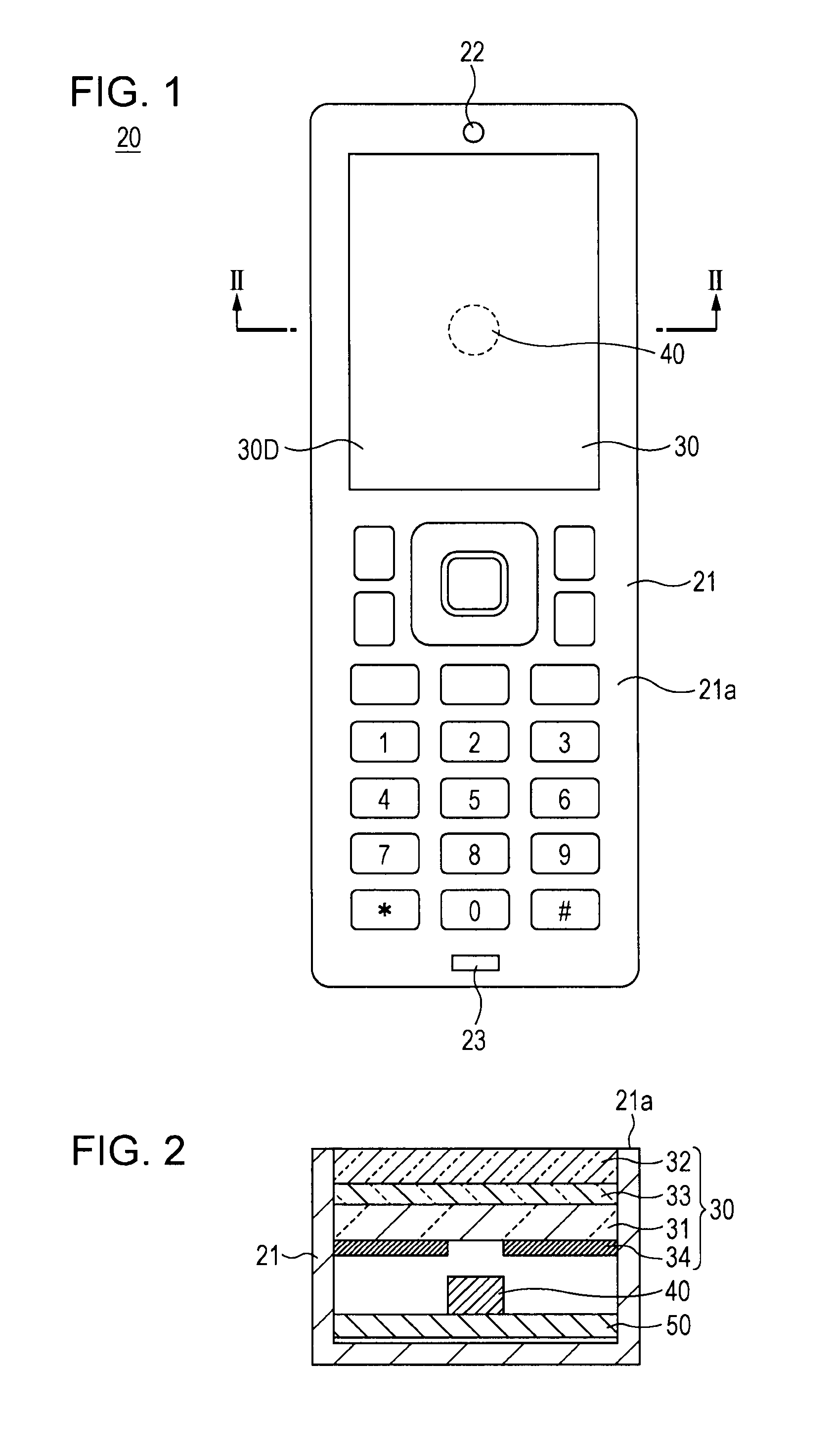
[0022]According to the embodiment of the disclosure, the sensor is provided on the back surface of the display screen. Therefore, an area for separately providing the sensor is not necessary on the surface where the display screen is provided, so that it is possible to increase the size of the display screen.
[0024]In the case where an optical sensor such as the illuminance sensor is used as the sensor, it is possible to detect the light transmitting through a portion as the display screen. Therefore, it is possible to perform optimal correction such as the case where the luminance of the display screen is corrected using the output of the illuminance sensor.
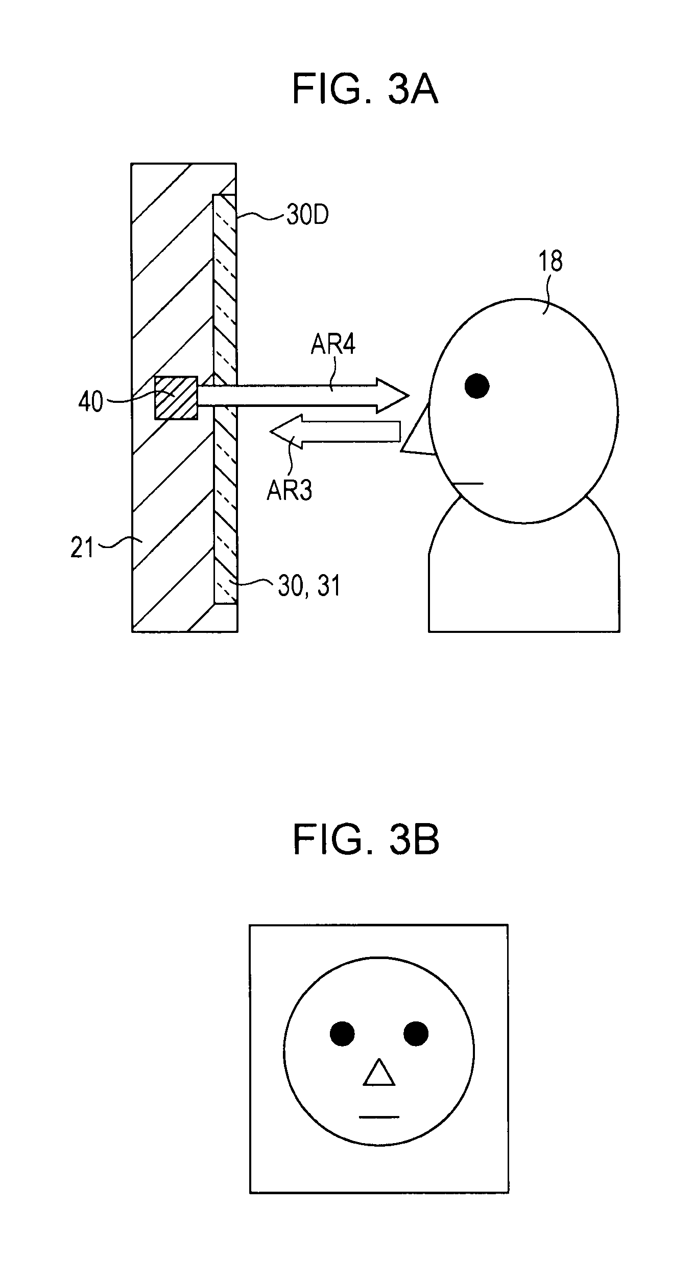
[0025]According to the present disclosure, since the sensor is provided on the back surface of the display screen, it is possible to increase the size of the display screen. Since the incident light through the display screen is received by the sensor, it is possible to obtain effects not being obtained in the related art. For example, when the sensor is a camera element, it is possible to obtain a front image for a user from the camera element. In addition, in the case where the luminance of the display screen is adjusted using the output from the illuminance sensor as an example of the sensor, it is possible to perform optimal adjustment.

Problems solved by technology

For this reason, the luminance may not be optimally adjusted when the user sees the display screen 14.
Therefore, it may fail to provide an optimal display screen luminance to a user 1.
For this reason, it is necessary to prepare an area of the display screen 14 of the display device in a separate area from the sensor arrangement area, and thus, disadvantageously, the size of the display screen is reduced that much.
Furthermore, in the related art, since the illuminance sensor for correcting the luminance of the display screen is provided in a separate area from the display screen, it is difficult to optimally adjust the luminance correction of the display screen.

Method used


Image

  • Sensor-equipped display apparatus and electronic apparatus
  • Sensor-equipped display apparatus and electronic apparatus
  • Sensor-equipped display apparatus and electronic apparatus

Examples


first embodiment

Modified Example of First Embodiment

[0102]In addition, the disclosure is not limited to the configuration in which the print layer is provided on the back surface of the transparent display device 31 as a way for visually obscuring the camera element 40 by way of an example of a sensor on the back surface of the transparent display device 31. For example, the same print layer may be provided on the surface of the substrate 50 where the camera element 40 is provided (the surface facing the back surface of the transparent display device 31) without providing the print layer 34 on the back surface of the transparent display device 31.

[0103]In addition, instead of the print layer 34, a sheet having the same optical reflection properties as that of the print layer 34 may be arranged on the back surface of the display screen of the transparent display device 31.

[0104]In addition, the entire surface of the substrate 50 (including the camera element 40) where the camera element 40 is provid...

second embodiment

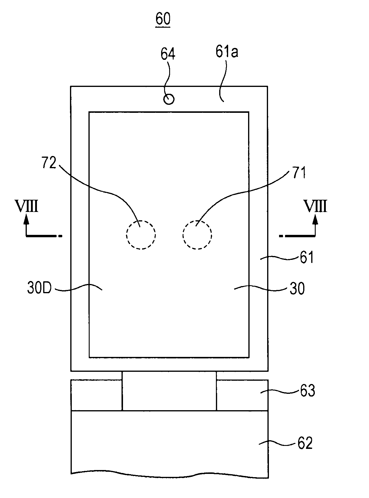
[0110]In the aforementioned first embodiment, the camera element is exemplarily arranged as a sensor on the back surface of the display screen. On the contrary, in the second embodiment, an illuminance sensor and a proximity sensor are provided as the sensor.

[0111]FIG. 7 is a diagram for describing an exemplary appearance of an electronic apparatus according to the second embodiment, in which a foldable mobile phone terminal 60 is exemplified. In the foldable mobile phone terminal 60 in this example, the upper casing 61 and the lower casing 62 are openably assembled about the rotation hinge 63 of the rotation hinge portion 63. In FIG. 7, the foldable mobile phone terminal 60 is opened at a predetermined angle, and the internal face 61a of the upper casing 61 is shown from a perpendicular direction therefrom. FIG. 7 corresponds to FIG. 14B which shows a foldable mobile phone terminal of the related art. FIG. 8 is a cross-sectional view taken along the line VIII-VIII for illustrating ...

third embodiment

[0132]The third embodiment describes an example that a predetermined input manipulation is reliably detected using a sensor by displaying a guide indication for a predetermined input manipulation from a user on the display screen using the sensor provided on the back surface of the display screen, for example, in the case where the sensor detects a predetermined input manipulation from a user.

[0133]For example, in the case where a user's fingerprint is read by a fingerprint sensor, and fingerprint authentication of the corresponding user is executed, if an appropriate guide is not provided, a user who is not familiar with that may not know how to input the fingerprint.

[0134]The example of the third embodiment is made to allow even a user who is not familiar with the fingerprint authentication to readily execute an input manipulation for the fingerprint authentication in the mobile phone terminal capable of executing the fingerprint authentication.

[0135]FIG. 10 illustrates appearance...


PUM


Abstract

A sensor-equipped display apparatus including a light-transmissive display screen, a sensor that detects light passing through the light-transmissive display screen, and a material that visually obscures the sensor when viewed through the light-transmissive display screen.

Description

CROSS REFERENCE TO RELATED APPLICATION[0001]The present application claims the benefit of the earlier filing date of U.S. Provisional Patent Application Ser. No. 61 / 384,964 filed on Sep. 21, 2010, the entire contents of which is incorporated herein by reference.BACKGROUND OF THE DISCLOSURE[0002]1. Field of the Disclosure[0003]The present disclosure relates to a display apparatus having a sensor such as a camera element or a light quantity sensor and an electronic apparatus having the same.[0004]2. Description of the Related Art[0005]Camera-equipped mobile phone terminals are being widely used, and mobile phone terminals having a so-called video phone function are also used (for example, refer to Japanese Unexamined Patent Application Publication No. 2007-201823). FIGS. 14A and 14B illustrate the appearance of an exemplary mobile phone terminal having a video phone function. FIGS. 14A and 14B show the case of a foldable mobile phone terminal 10, in which the upper and lower casings 1...

Claims


Application Information

Patent Timeline
IPC IPC(8): G09G5/02G09G5/00
CPCH04M1/0266H04M2250/12H04N7/144H04M1/0264
Inventor OGITA, TAKESHITAKANASHI, SHINTAKATSUKA, SUSUMU
Owner SONY CORP
Learn More