
Cover for airbag apparatus

a technology for airbags and covers, applied in the field of covers, can solve the problems of affecting the deployment performance of airbags

Inactive Publication Date: 2012-03-29
TOYODA GOSEI CO LTD
View PDF13 Cites 3 Cited by
  • Summary
  • Abstract
  • Description
  • Claims
  • Application Information

AI Technical Summary

Benefits of technology

[0014]The invention has been made to solve the above problems. An object of the invention is to provide a cover for an airbag apparatus capable of suppressing a lid part from becoming an obstacle to inflation of an airbag and thus appropriately deploying the airbag even when a passenger takes a posture coming close to the airbag.
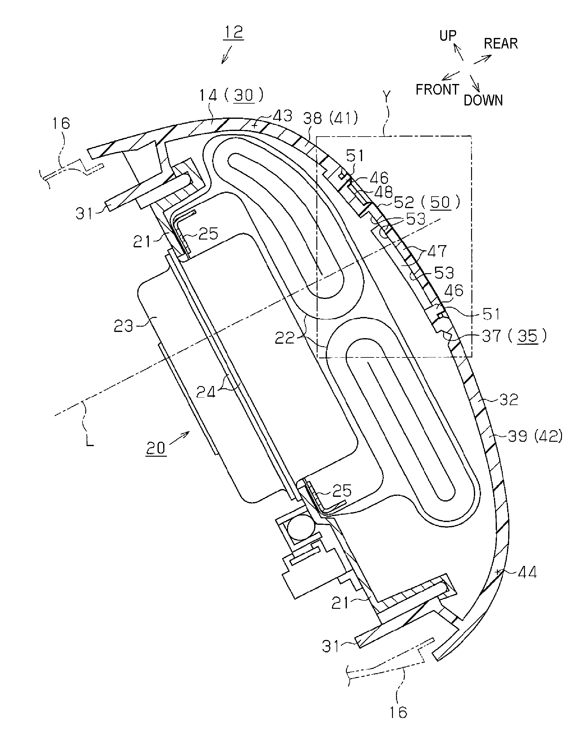
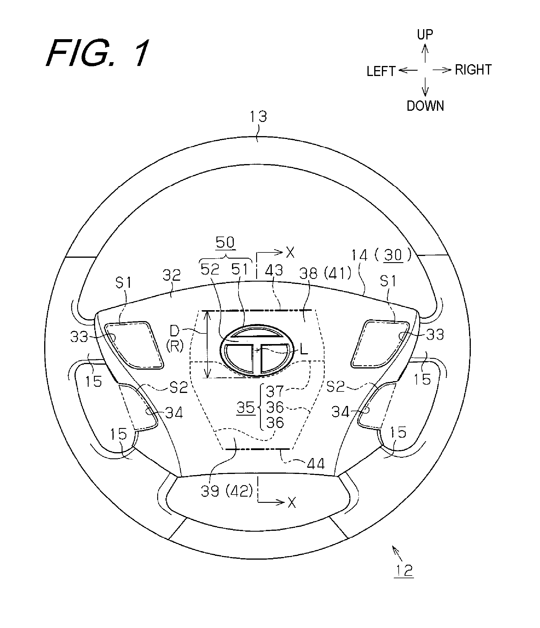
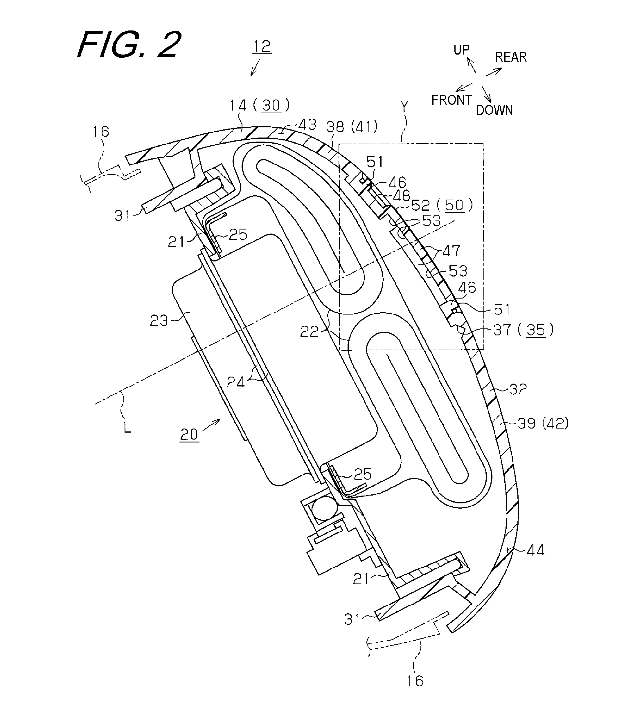
[0024]According to the above configuration, at a normal state in which the shock is not applied to the vehicle, the airbag is not inflated and is covered from the passenger side by the cover main body part. In addition, by the decorative part stacked to the passenger side of the cover main body part, it is possible to improve the design of the cover for an airbag apparatus.
[0042]As a result, the upper lid part, which is upward opened (rotated) with accompanied by the decorative part, is difficult to become an obstacle to the upward inflation of the airbag.
[0047]According to the cover for an airbag apparatus of the invention, even when the passenger takes a posture coming close to the airbag apparatus, it is possible to suppress the lid part from becoming an obstacle to the inflation of the airbag and thus to appropriately deploy the airbag.

Problems solved by technology

In this case, the upper lid part becomes an obstacle to the upward inflation of the airbag, thereby influencing the deployment performance of the airbag.
In this case, the lower lid part becomes an obstacle to the downward inflation of the airbag, thereby influencing the deployment performance of the airbag.
The above problems are not limited to the airbag apparatus that is provided to the steering wheel and thus protects the driver from the shock, and may be also commonly caused in an airbag apparatus for an assistant driver's seat and a side airbag apparatus.

Method used


Image

  • Cover for airbag apparatus
  • Cover for airbag apparatus
  • Cover for airbag apparatus

Examples


Embodiment Construction

[0054]Hereinafter, an illustrative embodiment in which a cover for an airbag apparatus of the invention is applied to a steering wheel having an airbag apparatus attached thereto, which airbag apparatus is mounted to a vehicle, will be described with reference to the drawings. As shown in at least one of FIGS. 1 and 6, a steering shaft 11 that is rotated about a rotating axis line L is obliquely provided at a front of a driver's seat of a vehicle (at a left side in FIG. 6) so that it is higher at the driver's seat (at a right side in FIG. 6). A steering wheel 12 is integrally and rotatably mounted to a rear end of the steering shaft 11. The steering wheel 12 has a rim part (which is also referred to as a steering wheel part and a ring part) 13, a pad part 14 and a spoke part 15. The rim part 13 is a member that is gripped and steered by a driver, and has a substantial ring shape about the steering shaft 11 (refer to FIG. 1). Since the steering shaft 11 is inclined as described above...


PUM


Abstract

A cover for an airbag apparatus with a lateral line portion of a tear line partitioning regions on a cover main body located near a decorative part. The cover main body part having the tear line is resin-molded using a soft film having a shape corresponding to the decorative part as an insert. The cover main body part is fractured along the tear line when inflation pressure of the airbag is applied thereto, so that a plurality of lid parts corresponding to the regions is formed. Each lid part opens about a connection portion to a remaining part of the cover main body part, which portion serves as a hinge portion. On a backside of the cover main body part, at least a portion of the part corresponding to the decorative part is provided with a bore portion.

Description

BACKGROUND OF THE INVENTION[0001]1. Field of the Invention[0002]The invention relates to a cover that covers an airbag apparatus mounted to a vehicle such as automobile, and more particularly, to a cover for an airbag apparatus having a tear line (fracture-expected portion) to be fractured by an airbag and a decorative part such as emblem.[0003]2. Related Art[0004]In vehicles such as automobiles, it is necessary to protect a driver from shock when the shock is applied from the front due to a front end collision. Accordingly, a steering wheel configuring a part of a steering apparatus has been adopted in which an airbag apparatus is assembled in a pad of the steering wheel.[0005]In addition, as a cover for the airbag apparatus, a cover has been known which has a cover main body part covering the airbag from a driver side and a rigid decorative part fixed to the cover main body part from the driver side. The decorative part is used to improve the designs of the cover for an airbag app...

Claims


Application Information

Patent Timeline
Patent Type & Authority Applications(United States)
IPC IPC(8): B60R21/20
CPCB60R21/21656
Inventor HAYASHI, MIKINEJOH, MASAKO
Owner TOYODA GOSEI CO LTD
Learn More