Fiber Optic Cable Assembly And Methods

Inactive Publication Date: 2012-03-29
BEL FUSE MACAO COMML OFFSHORE
View PDF4 Cites 8 Cited by
  • Summary
  • Abstract
  • Description
  • Claims
  • Application Information

AI Technical Summary

Benefits of technology

[0009]Accordingly, one object of an embodiment of the present invention i

Problems solved by technology

Strength members such as central strength members and/or aramid strength members within the cable are used in fiber optic cables to keep any tensile installation load from being applied to the light carrying core, which is generally formed of glass, as this can cause reduced performance and possibly system failure.
As the complexity of fiber optic connections increases, fiber management becomes increasingly more difficult.
As the number of connections at a distribution panel increases, the possibility of errors in connecting the individual optical fibers to the couplers also increases.
Exchanging or changing the locations at which in

Method used


Image

  • Fiber Optic Cable Assembly And Methods
  • Fiber Optic Cable Assembly And Methods
  • Fiber Optic Cable Assembly And Methods

Examples


Example

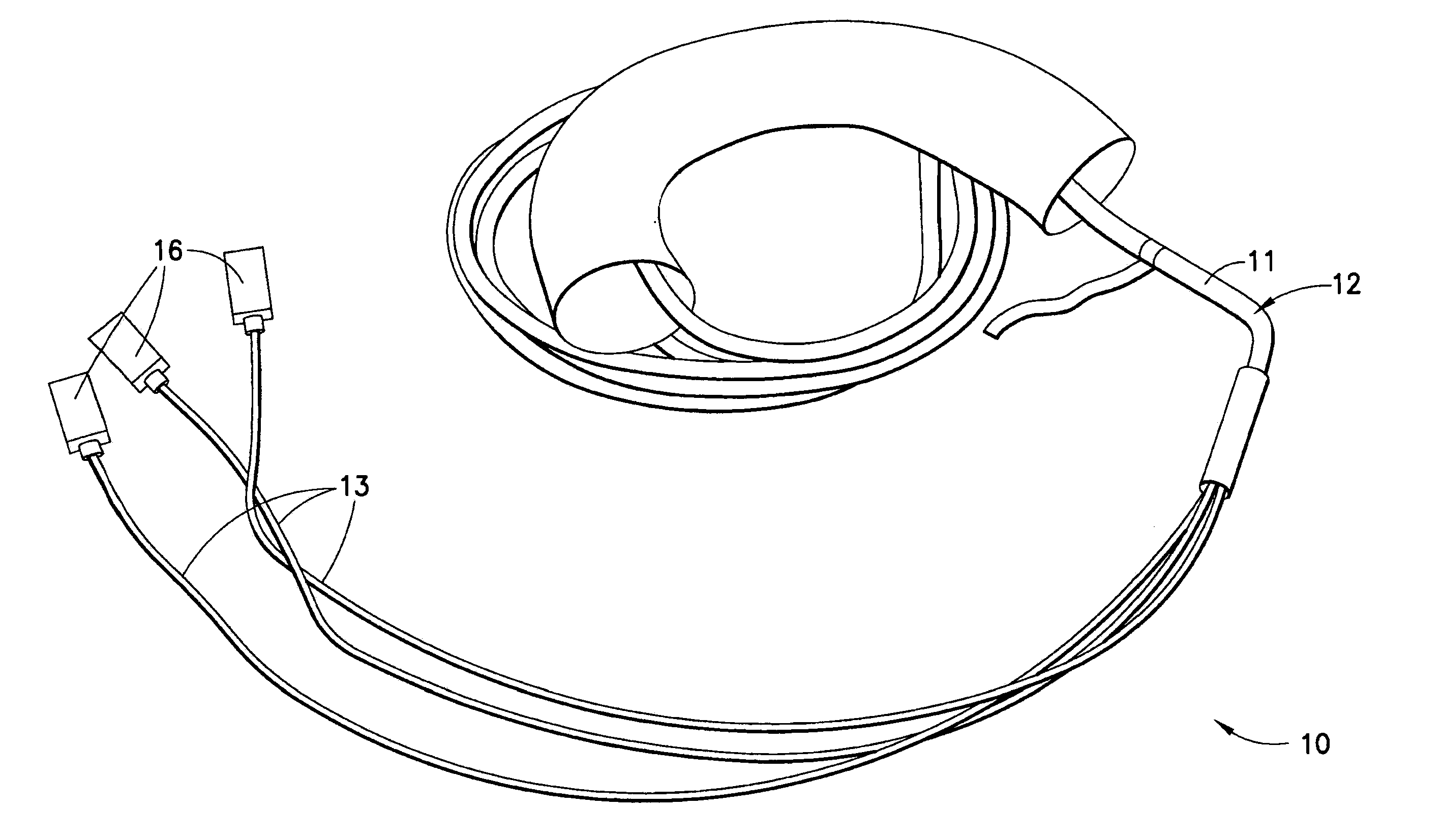
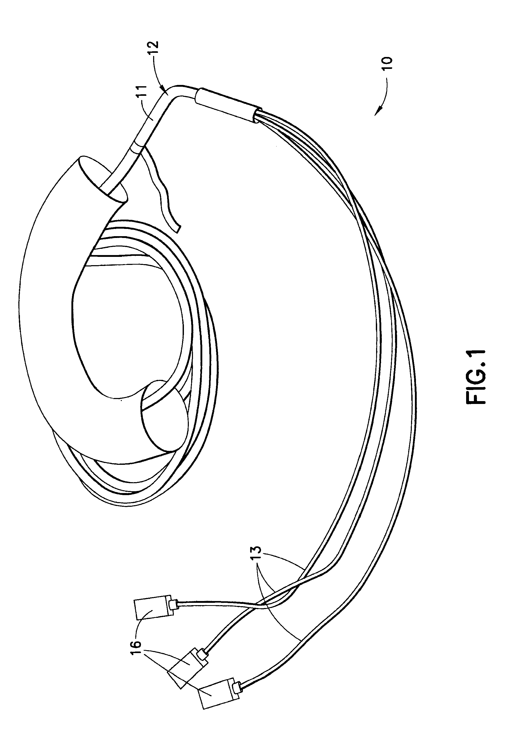
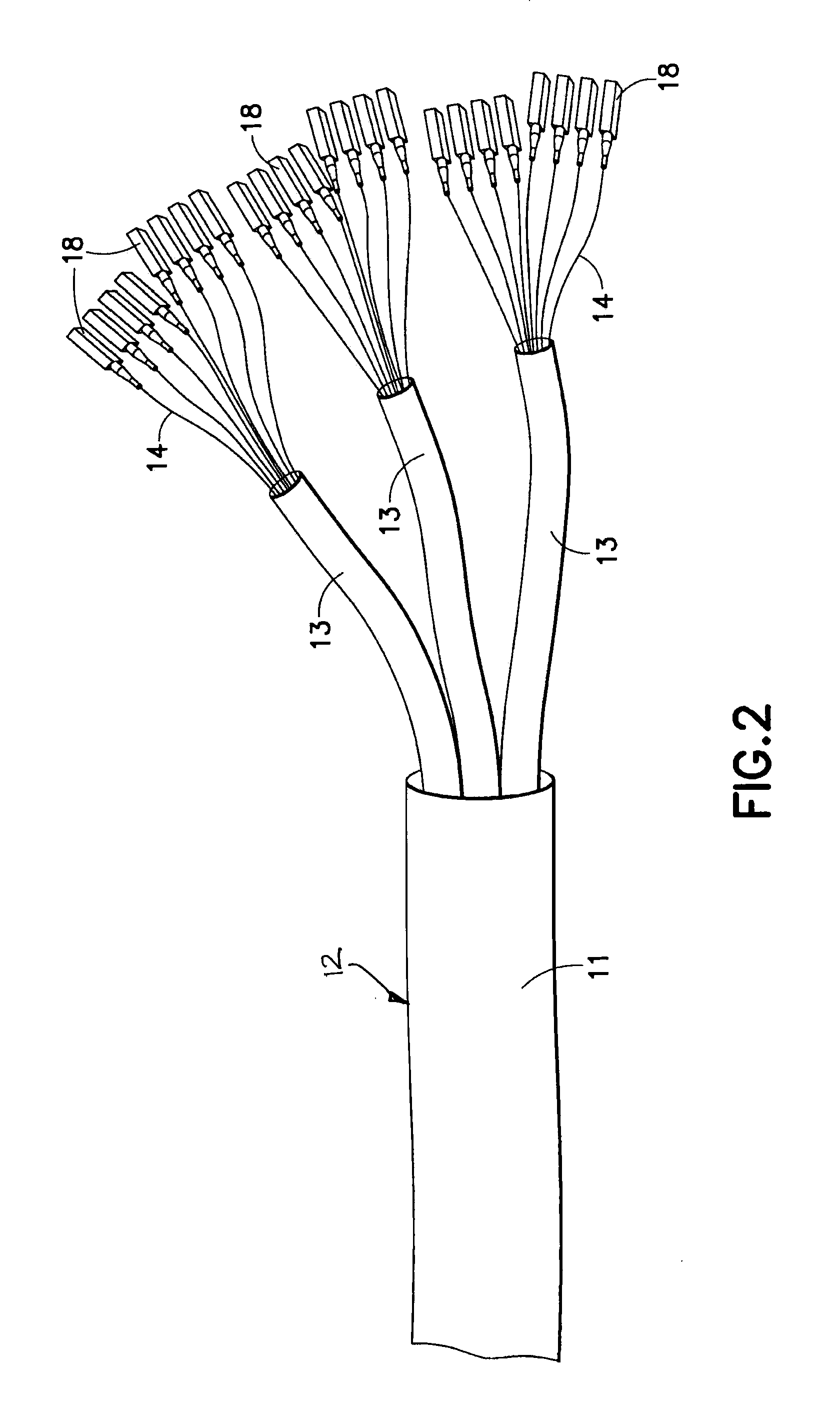
[0045]Referring now to the drawings wherein like reference characters designate identical or corresponding parts throughout the several views, a fiber optic cable assembly in accordance with an embodiment of the present invention, generally designated 10, is illustrated in FIG. 1. Referring to FIGS. 1 and 2, the fiber optic cable assembly 10 includes a fiber optic cable 12 having an outer sheath 11 (FIG. 2) in which three inner sheaths 13 are enclosed, each inner sheath 13 surrounding eight optical fibers 14 so that the cable 12 includes a total of twenty-four optical fibers 14. Each of the optical fibers is pre-terminated by a respective optical fiber connector 18. The connectors 18 may be any one of the several industry standard types, such as LC, SC, ST, MPO or the like. The connectors shown in the illustrated embodiment comprise LC type connectors, each of which terminates a single optical fiber 14. The fiber optic cable assembly 10 further includes three interconnection modules...


PUM

PropertyMeasurementUnit
Lengthaaaaaaaaaa

Abstract

A fiber optic cable assembly including at least one fiber optic cable including a plurality of optical fibers, a plurality of connectors pre-terminating at least some of the optical fibers, at least two interconnection modules having respective couplers, and wherein at least some of the connectors of the pre-terminated optical fibers of the at least one fiber optic cable are received and held in a coupler of each of the at least two interconnection modules. The cable is pulled through the ducts, conduit, etc. with the interconnection modules being separated from each other. The interconnection modules are small enough so that it is practical for them to be covered by a protective grip or boot and pulled through ducts, conduit or the like. The interconnection modules are preferably provided with attachment elements for attaching the interconnection modules to each other after the cable pull is completed to form an integrated modular array.

Description

FIELD OF THE INVENTION[0001]This invention relates generally to fiber optic cabling and, more particularly, to a pre-terminated fiber optic cable assembly and methods for making and installing a fiber optic cable assembly.BACKGROUND OF THE INVENTION[0002]The use of fiber optic cables for carrying transmission signals is widespread, such as in the telecommunication industry. There are several types of fiber optic cables. Typically, a fiber optic cable may include at least one optical fiber composed of a light carrying core and a cladding that traps the light in the core. A plastic buffer coating may surround the fiber for protection and the fiber covered by the buffer coating is situated in an outer jacket. Distribution cable, breakout cable and loose tube cable are examples of fiber optic cable used in premises installations that contain a plurality of optical fibers.[0003]Generally, fiber optic cable is installed in premises by pulling an end of the cable through ducts, conduits, p...

Claims


Application Information

Patent Timeline
IPC IPC(8): G02B6/36B23P19/00G02B6/26
CPCG02B6/3825Y10T29/49826G02B6/3879
Inventor SELL, NATHAN
Owner BEL FUSE MACAO COMML OFFSHORE
Why Eureka
Try Eureka