Wireless power transfer apparatus and method thereof

wireless technology, applied in the direction of battery data exchange, exchanging data chargers, inductances, etc., can solve the problem of limited total power transmitted by a wireless power transmitter to some maximum

Active Publication Date: 2012-04-05
INTEL CORP
View PDF14 Cites 415 Cited by
  • Summary
  • Abstract
  • Description
  • Claims
  • Application Information

AI Technical Summary

Problems solved by technology

In general, the total power transmitted by a wireless power transmitte

Method used


Image

  • Wireless power transfer apparatus and method thereof
  • Wireless power transfer apparatus and method thereof
  • Wireless power transfer apparatus and method thereof

Examples


Embodiment Construction

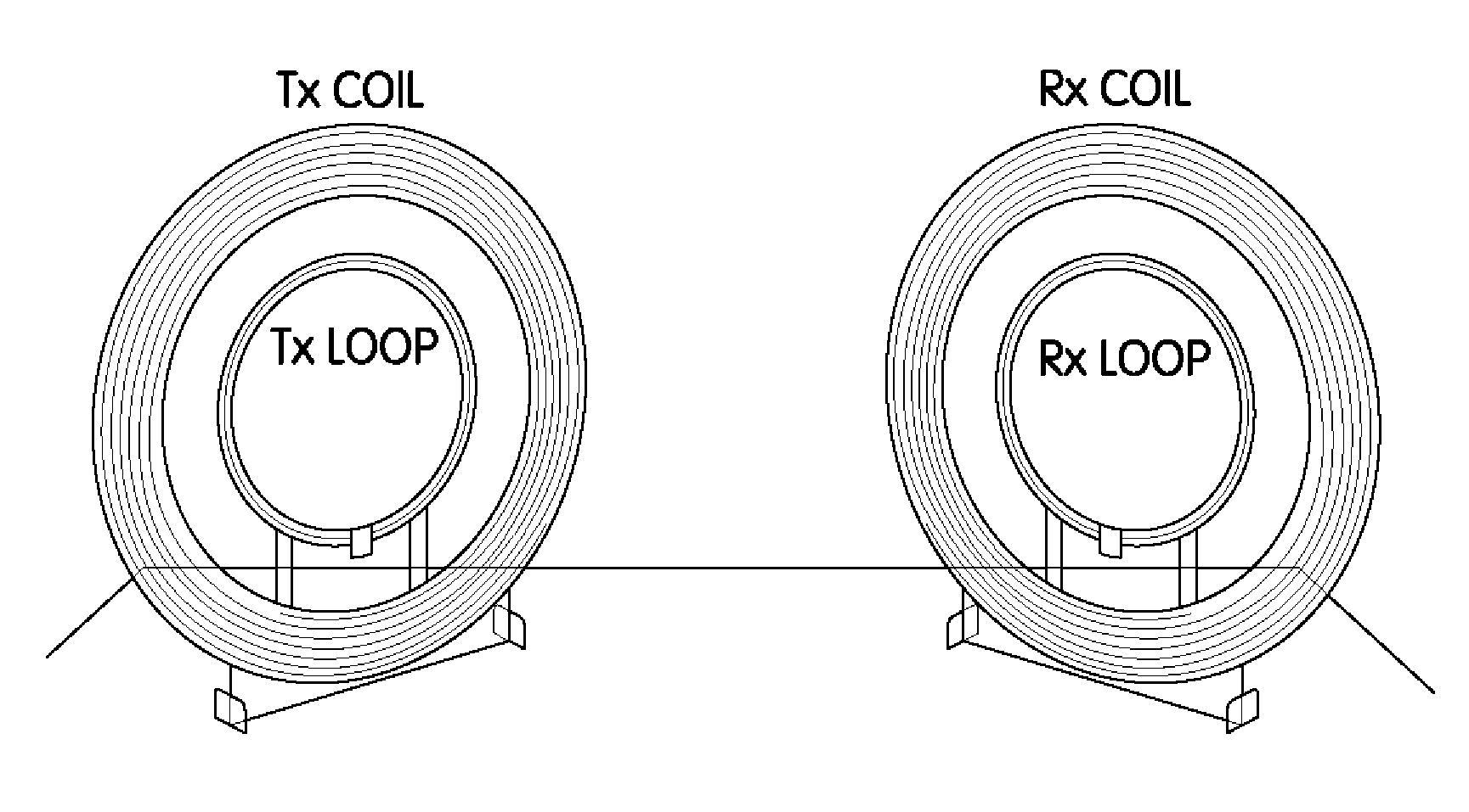
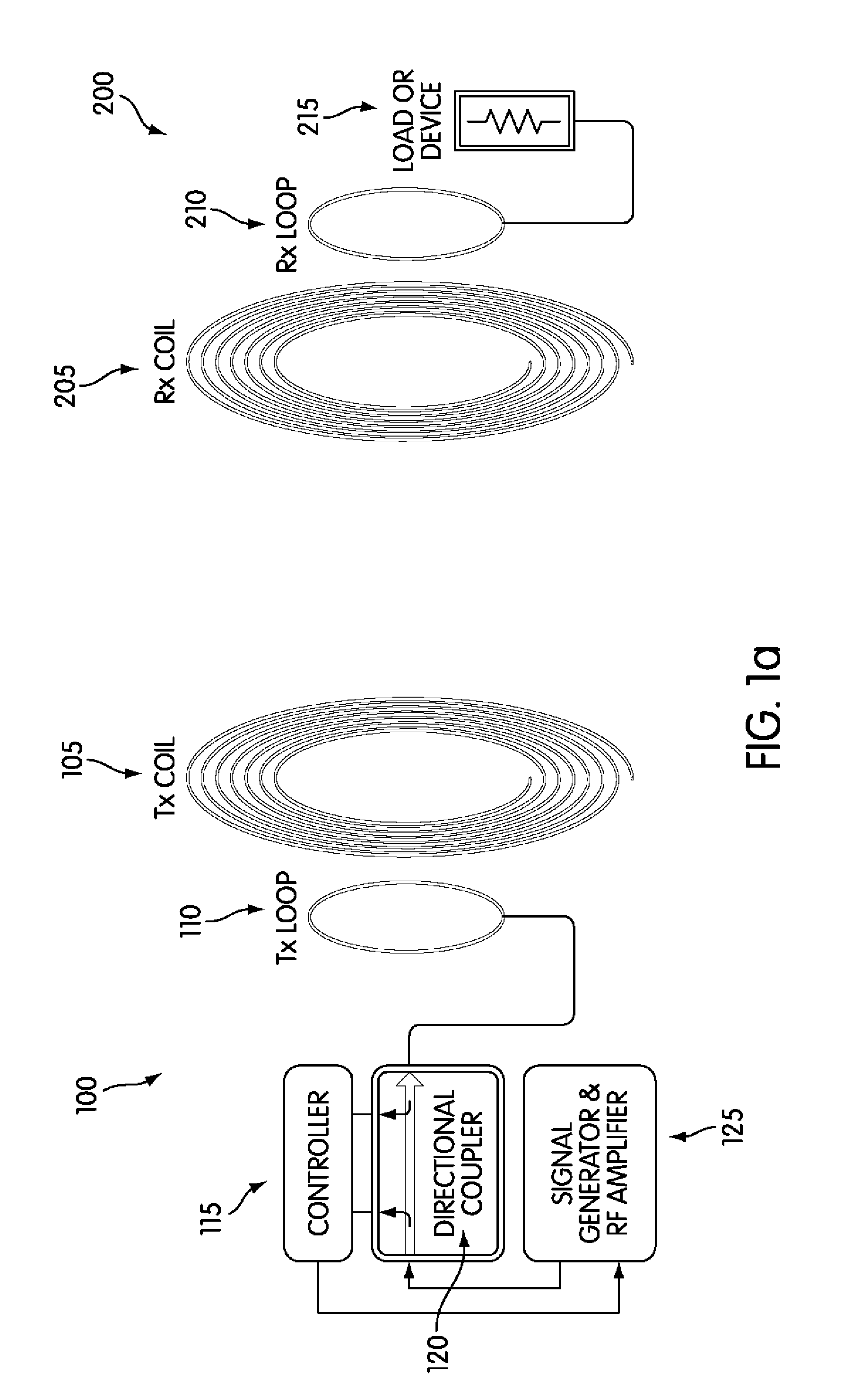
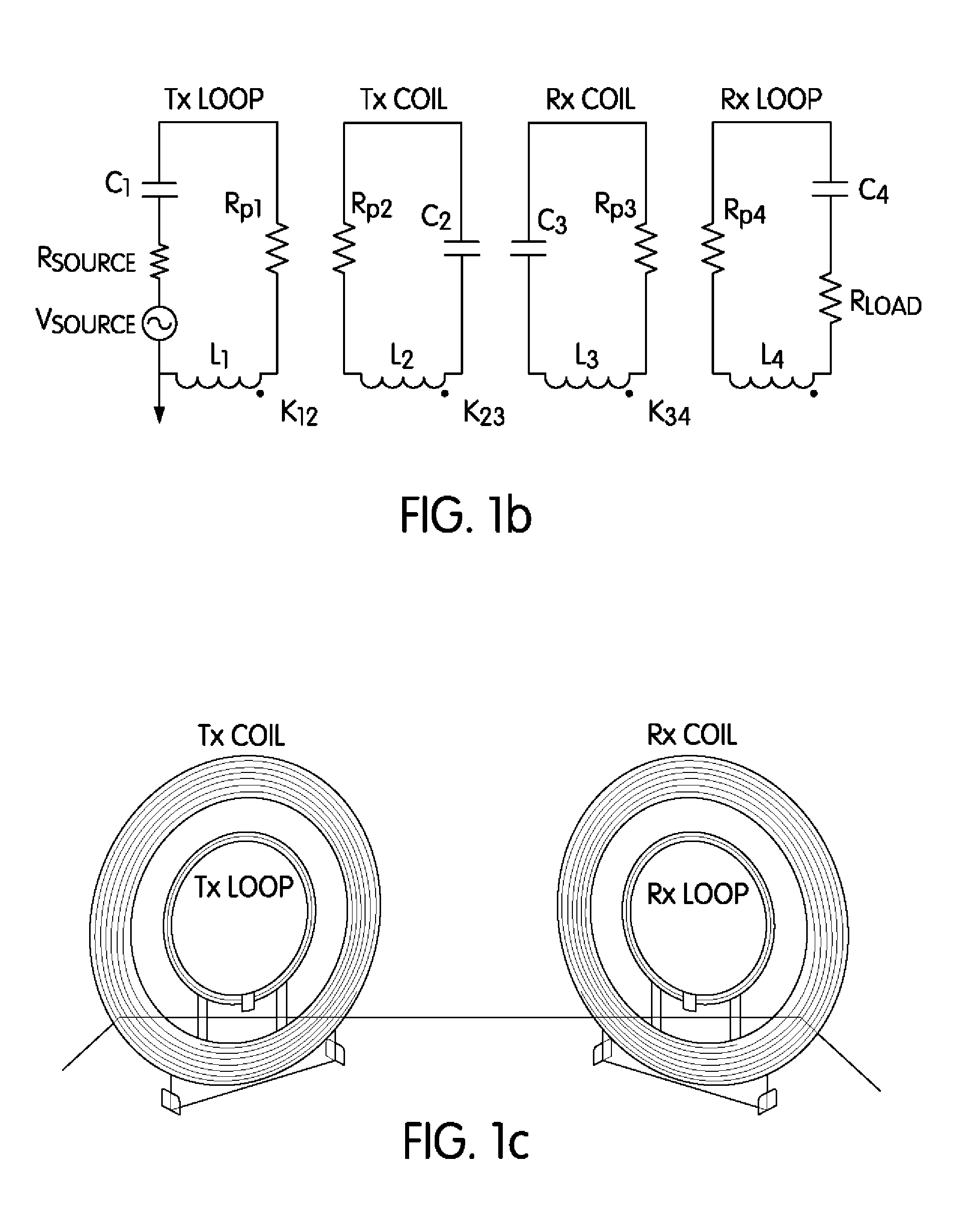
[0030]In the description that follows, like components have been given the same reference numerals, regardless of whether they are shown in different embodiments. To illustrate an embodiment(s) of the present disclosure in a clear and concise manner, the drawings may not necessarily be to scale and certain features may be shown in somewhat schematic form. Features that are described and / or illustrated with respect to one embodiment may be used in the same way or in a similar way in one or more other embodiments and / or in combination with or instead of the features of the other embodiments.

[0031]In accordance with various embodiments of this disclosure, a receiving device is disclosed that includes a receiving antenna configured to wirelessly receive power transmitted by a transmitting device and arranged to associate or dissociate with the transmitting device.

[0032]The receiving device can further include a load electrically coupled to the receiving antenna that is configured to be ...


PUM


Abstract

In accordance with various aspects of the disclosure, a method and apparatus is disclosed that includes features of a receiving antenna configured to wirelessly receive power transmitted by a transmitting device and arranged to associate or dissociate with the transmitting device.

Description

[0001]This application is a continuation-in-part of pending U.S. application Ser. No. 12 / 754,954 filed on Apr. 6, 2010 which is a continuation-in-part of pending U.S. application Ser. Nos. 12 / 544,974 and 12 / 544,956 both filed on Aug. 20, 2009, which claims benefit under 35 U.S.C. §119(e) from U.S. Provisional Application No. 61 / 189,502 filed on Aug. 20, 2008. The disclosure of all of the foregoing U.S. patent applications are herein incorporated by reference in their entirety.BACKGROUND[0002]This disclosure relates generally to the field of power transmission, and in particular, to a method and apparatus for transmitting and receiving power wirelessly.[0003]In general, the total power transmitted by a wireless power transmitter will be limited to some maximum power by e.g. regulatory limitations. There are generally two approaches to deliver power to multiple receivers from a single transmitter.[0004]The first is for all receivers to receive a portion of the total transmitted power ...

Claims


Application Information

Patent Timeline
IPC IPC(8): H02J17/00
CPCH02J5/005H02J50/80H04B5/0037H02J7/00034H02J50/12H02J50/402H02J50/005
Inventor COOPER, EMILY B.SMITH, JOSHUA R.SAMPLE, ALANSON P.
Owner INTEL CORP
Why Eureka
Try Eureka