Stator with cooling system and associated motor

a cooling system and stator technology, applied in the direction of dynamo-electric machines, magnetic circuit shapes/forms/construction, supports/enclosements/casings, etc., can solve the problems of reducing the ability to cool the electric motor with air, air cooling is not practical, and air cooling is often considered inadequa

Inactive Publication Date: 2012-04-05
CATERPILLAR INC
View PDF3 Cites 23 Cited by
  • Summary
  • Abstract
  • Description
  • Claims
  • Application Information

AI Technical Summary

Problems solved by technology

However, in certain applications, air cooling is not practical on account of the blower and ducting requirements.
Air cooling is often considered inadequate, particularly for electric motors on powerful automobiles or machines that are subject to varied temperature ranges and environments.
The air for cooling may be dusty or dirty or the electric motors themselves may become coated with mud and dust, reducing the ability to cool the electric motors with air.
Although liquid cooling enables the use of fluids readily available on the vehicle and is exceedingly effective in cooling electric motors, it is a much more expensive and complex way of cooling.
The complexity associated with liquid cooling is generally on account of the routing of the coolant through and over the electric motors or generators to achieve adequate cooling.
Though the misaligned pins generate turbulence and may enable the cooling fluid to reach a greater area, they may overly reduce the flow of the cooling fluid over the electric motors or generators, causing inefficiency.

Method used


Image

  • Stator with cooling system and associated motor
  • Stator with cooling system and associated motor
  • Stator with cooling system and associated motor

Examples


first embodiment

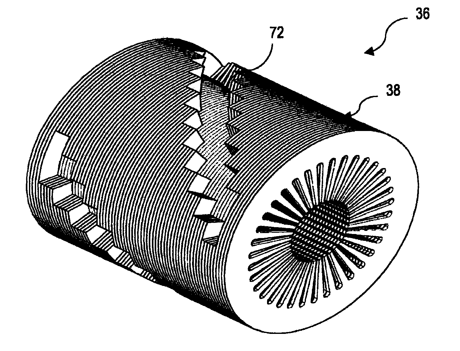
[0028]FIG. 4 is an isometric view of a stator 36 defining a substantially helical channel 74 in accordance with the invention. The laminates 38 are arranged such that the notches 66 form a substantially helical channel 74 on the outer periphery of the stator 36. In the embodiment illustrated, each laminate 38 has a plurality of notches 66 that are uniformly distributed along its peripheral edge 16, the plurality of notches 66 forming a plurality of channels along the periphery of the stator 36. Also in the embodiment illustrated, the plurality of laminates 38 includes a plurality of laminate subsets 72, wherein the laminates 38 in each laminate subset 72 are arranged with the notches 66 aligned to define a passage 73. The laminate subsets 72 are arranged such that the passages 73 defined by the laminate subsets 72 form a substantially helical channel 74 along the periphery of the stator 36.

[0029]In the embodiment illustrated, each of the laminate subsets 72 is separated from one or ...

second embodiment

[0030]FIG. 5 is an isometric view of a stator 36 defining a substantially helical channel 74 in accordance with the invention. In the embodiment illustrated in FIG. 5, the notch 66 defined by each of the transition laminates 64 is smaller in width than the passages 73 formed by each of the laminate subsets 72.

third embodiment

[0031]FIG. 6 is an isometric view of a stator 36 defining a substantially helical channel 74 in accordance with the invention. In the embodiment illustrated in FIG. 6, the notches 66 defined by each of the plurality of laminates are substantially identical and the plurality of laminates 38 include laminate subsets 72. The laminate subsets 72 are stacked one on top of the other without any transition laminate to form a substantially helical channel 74.


PUM


Abstract

An electric motor is disclosed that includes a rotor having an axis and being rotatable about the axis. A stator is positioned about the rotor and includes a plurality of laminates with each laminate in the plurality of laminates including a peripheral edge defining a notch. The plurality of laminates includes a plurality of laminate subsets, with the laminates in each laminate subset arranged with the notches aligned to define a passage. The laminate subsets are arranged such that the passages defined by the laminate subsets form a substantially helical channel along the periphery of the stator.

Description

TECHNICAL FIELD[0001]The present disclosure relates generally to a cooling system for an electrical motor. More particularly, the disclosure relates to a cooling system for a stator of an electrical motor.BACKGROUND[0002]For electric motors or generators, particularly those used in stationary applications, reasonable cooling is accomplished by using air cooling and motor housings that serve as heat sinks. Traction motors are typically forced-air cooled with a blower. Ducting is used to route air into and out of the motor or generator. However, in certain applications, air cooling is not practical on account of the blower and ducting requirements.[0003]Air cooling is often considered inadequate, particularly for electric motors on powerful automobiles or machines that are subject to varied temperature ranges and environments. The air for cooling may be dusty or dirty or the electric motors themselves may become coated with mud and dust, reducing the ability to cool the electric motor...

Claims


Application Information

Patent Timeline
Patent Type & Authority Applications(United States)
IPC IPC(8): H02K1/20
CPCH02K1/20
Inventor IUND, TREVOR
Owner CATERPILLAR INC
Why Eureka
Try Eureka