System for nested entropy encoding

a technology of entropy and encoding, applied in the field of nested entropy encoding, can solve the problem that the necessary bit rate to preserve a desired quality is often too high for the transmission medium, and achieves the effect of preserving the desired quality and avoiding the transmission medium

Active Publication Date: 2012-04-05
DOLBY INT AB
View PDF14 Cites 107 Cited by
  • Summary
  • Abstract
  • Description
  • Claims
  • Application Information

AI Technical Summary

Problems solved by technology

Modern video transmission and display systems, and particularly those systems that present high-definition content, require significant data compression in order to produce a visually acceptable motion picture, because transmission media simply cannot transmit an uncompressed sequence of video

Method used


Image

  • System for nested entropy encoding
  • System for nested entropy encoding
  • System for nested entropy encoding

Examples


Embodiment Construction

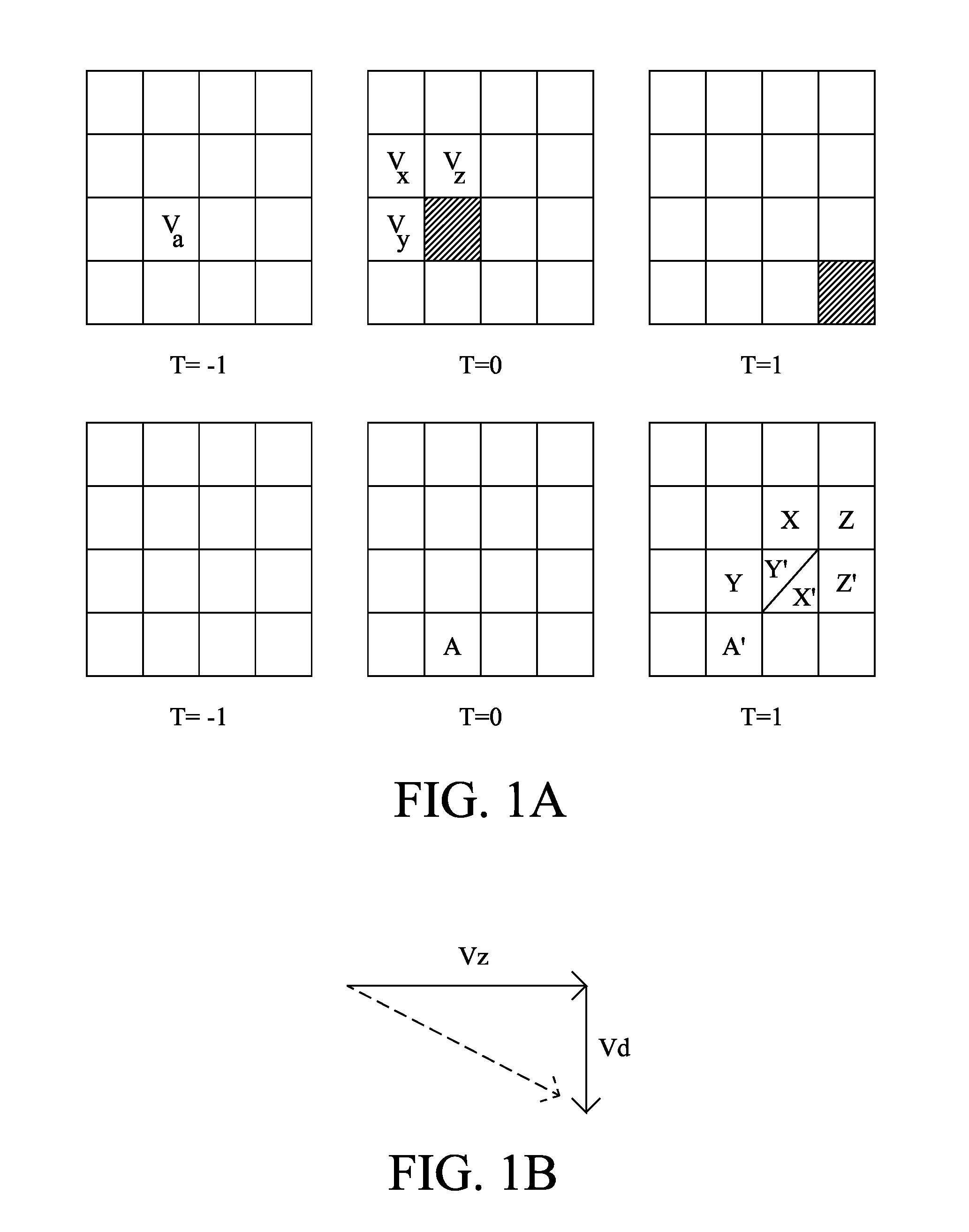
[0017]Referring to FIGS. 1A and 1B, a motion vector for a candidate block (shown in cross-hatch) in a current frame at T=0 points to the cross-hatched block in subsequent frame at t=1. This motion vector may be encoded with reference to a candidate set of motion vectors Va, Vx, Vy, and Vz. In this example, motion vector Va is a co-located motion vector in the preceding frame at t=−1 and points to block A in the current frame. Motion vectors VX, Vy, and Vz are previously-encoded motion vectors in the current frame and point to blocks X, Y, and Z, respectively, in the subsequent frame at T=1. FIG. 1A also shows the blocks A′, X′, Y′, and Z′ that the respective motion vectors would point to if used when encoding the candidate block.

[0018]As can be seen in FIG. 1B, using the motion vector competition (MVC) procedure, motion vector Vz would be selected to minimize the code length of the differential Vd, which in that instance, would only require a value of “1” in a single component (down...


PUM


Abstract

Methods and systems for improving coding efficiency of video.

Description

CROSS-REFERENCE TO RELATED APPLICATIONS[0001]None.BACKGROUND OF THE INVENTION[0002]Modern video transmission and display systems, and particularly those systems that present high-definition content, require significant data compression in order to produce a visually acceptable motion picture, because transmission media simply cannot transmit an uncompressed sequence of video frames at a fast enough rate to appear as continuous motion to the human eye. At the same time, and again to produce a visually-acceptable picture, the compression technique used should not unduly sacrifice image quality by discarding too much frame data.[0003]To achieve these dual, and conflicting goals, video compression and encoding standards such as MPEG and H.264 take advantage of temporal redundancy in the sequence of video frames. In other words, in the vast majority of video sequences of interest to a person, adjacent frames typically show the same objects or features, which may move slightly from one fr...

Claims


Application Information

Patent Timeline
IPC IPC(8): H04N7/26
CPCH04N19/52H04N19/91H04N19/513H04N19/46H04N19/44
Inventor SU, YEPINGSEGALL, CHRISTOPHER A.
Owner DOLBY INT AB
Why Eureka
Try Eureka