Power amplifier linearization method and apparatus

a technology of linearization method and power amplifier, which is applied in the direction of amplifier, amplifier, amplifier with semiconductor device/discharge tube, etc., can solve the problems of inability to recognize memory effects, power amplifiers with considerably low efficiency characteristics, and inability to ensure stable operation of transmitters, etc., to achieve and effective linearization of amplifiers

Active Publication Date: 2012-04-12
POSTECH ACAD IND FOUND
View PDF2 Cites 9 Cited by
  • Summary
  • Abstract
  • Description
  • Claims
  • Application Information

AI Technical Summary

Benefits of technology

[0038]Accordingly, the present invention has been made in an effort to solve the problems occurring in the related art, and an object of the present invention is to provide a method and apparatus for effectively linearizing an amplifier which has a plurality of distortion generating sources.

Problems solved by technology

In addition, a next generation mobile communication system uses a complicated modulation scheme in order to transmit a large amount of data to the user in a short time.
However, at this point, the power amplifier exhibits a considerably low efficiency characteristic.
This is because the stable operation of a transmitter is not ensured due to an increase of the heating value of the transmitter.
In addition, in a high output power, since the distortion component caused by the power amplifier itself is large, it is impossible to recognize a memory effect.
However, in the case of an amplifier, such as a Doherty amplifier, which includes distortion generating sources generating mutually different non-linear characteristics and memory effects, there is a limitation in a degree of linearization improvement when linearization according to the conventional linearization manner is performed as in the amplifier compensator 210.

Method used


Image

  • Power amplifier linearization method and apparatus
  • Power amplifier linearization method and apparatus
  • Power amplifier linearization method and apparatus

Examples


first embodiment

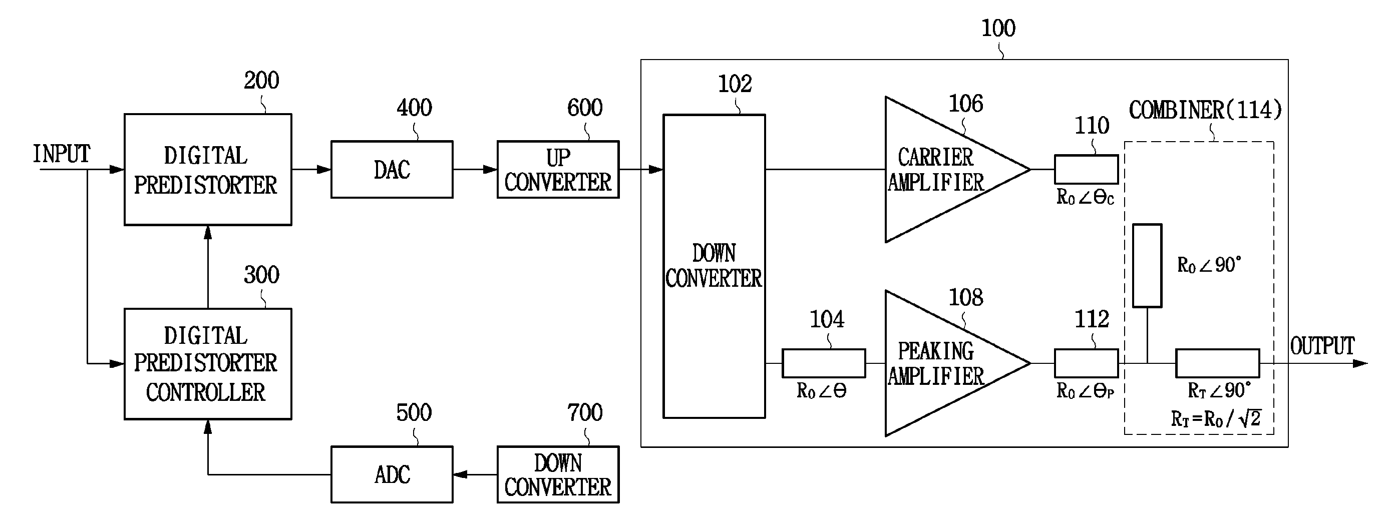
[0059]FIG. 7a is a block diagram illustrating the inner configuration of a digital predistorter according to the present invention.

[0060]Referring to FIG. 7a, the digital predistorter includes a signal division unit 220, a first amplifier compensation unit 222, a second amplifier compensation unit 224, and a signal combination unit 226.

[0061]The signal division unit 220 compares the amplitude of an input signal with a predetermined threshold value, outputs the input signal to the first amplifier compensation unit 222 or the second amplifier compensation unit 224. That is to say, in the case where the amplitude of an input signal has a value in a range from 0 to 1, the signal division unit 220 outputs an input signal to the first amplifier compensation unit 222 when the input signal is in a range from 0 to the threshold value, and outputs an input signal to the second amplifier compensation unit 224 when the input signal is in a range from the threshold value to 1. Taking a Doherty a...

second embodiment

[0066]FIG. 7b is a block diagram illustrating the inner configuration of a digital predistorter according to the present invention.

[0067]Referring to FIG. 7b, the digital predistorter includes a signal division unit 220, a first amplifier compensation unit 222, a second amplifier compensation unit 224, a signal combination unit 226, and an amplifier compensation unit 228.

[0068]The signal division unit 220, first amplifier compensation unit 222, second amplifier compensation unit 224, and signal combination unit 226 perform the same operations as those in FIG. 7a, so a detailed description thereof will be omitted.

[0069]The amplifier compensation unit 228 receives an inverse distortion signal, which has been created through the first amplifier compensation unit 222 and second amplifier compensation unit 224 and has been outputted from the signal combination unit 226, and then outputs an additional amplifier compensation signal.

[0070]The amplifier compensation unit 228 additionally com...


PUM


Abstract

Disclosed is a method and apparatus for linearizing a power amplifier using a digital signal process (DSP), and particularly, is a method and apparatus for effectively linearizing an amplifier which has a plurality of distortion generating sources. To this end, there is a plurality of compensation methods and compensation units which can generate inverse distortion signals corresponding to the distortion components outputted by the plurality of distortion generating sources, thereby making it possible to provide superior linearity.

Description

BACKGROUND OF THE INVENTION[0001]1. Field of the Invention[0002]The present invention relates to a power amplifier linearization method and apparatus, and more particularly, to a method and apparatus for effectively linearizing a power amplifier having a plurality of distortion generating sources.[0003]2. Description of the Related Art[0004]Recently, a power amplifier in a mobile communication system has been required to amplify a signal with high efficiency and high linear characteristics. In addition, a next generation mobile communication system uses a complicated modulation scheme in order to transmit a large amount of data to the user in a short time.[0005]Accordingly, the peak-to-average power ratio (PAPR) of the signal increases. Generally, in order to provide linear amplification, a power amplifier operates at a back off point equal to or greater than the peak-to-average power ratio of a signal.[0006]However, at this point, the power amplifier exhibits a considerably low eff...

Claims


Application Information

Patent Timeline
Patent Type & Authority Applications(United States)
IPC IPC(8): H03F1/26
CPCH03F1/0288H03F2201/3209H03F2200/321H03F1/3241
Inventor KIM, BUM MANMOON, JUNG HWAN
Owner POSTECH ACAD IND FOUND
Why Eureka
Try Eureka