LED light fixture with background lighting

a technology of led light fixtures and background lighting, which is applied in lighting applications, lighting heating/cooling arrangements, electric variable regulation, etc., can solve the problems of not being attractive and esthetic to look at lights, and customers' dislike of the look of multiple light dots

Active Publication Date: 2012-04-19
MARTIN PROFESSIONAL
View PDF1 Cites 34 Cited by
  • Summary
  • Abstract
  • Description
  • Claims
  • Application Information

AI Technical Summary

Benefits of technology

[0005]The object of the present invention is to solve the above described limitations related to prior art. This is achieved by an illumination device and method as described in the independent claims. The dependent claims describe possible embodiments of the present invention. The advantages and benefits of the present invention are described in the detailed description of the invention.

Problems solved by technology

The light fixtures typically create the lighting effect at a distance from the light fixture it self and the light fixture is thus not as interesting and esthetic to look at.
However this is very difficult as the housing of the fixtures typical dependents on physical requirements defined by the technical specifications of the fixture such as optics, mechanics, electronics, cooling etc.
Now that most LED fixtures have visible LEDs, some customers dislike the look of multiple light dots.

Method used


Image

  • LED light fixture with background lighting
  • LED light fixture with background lighting
  • LED light fixture with background lighting

Examples


Embodiment Construction

[0005]The object of the present invention is to solve the above described limitations related to prior art. This is achieved by an illumination device and method as described in the independent claims. The dependent claims describe possible embodiments of the present invention. The advantages and benefits of the present invention are described in the detailed description of the invention.

DESCRIPTION OF THE DRAWING

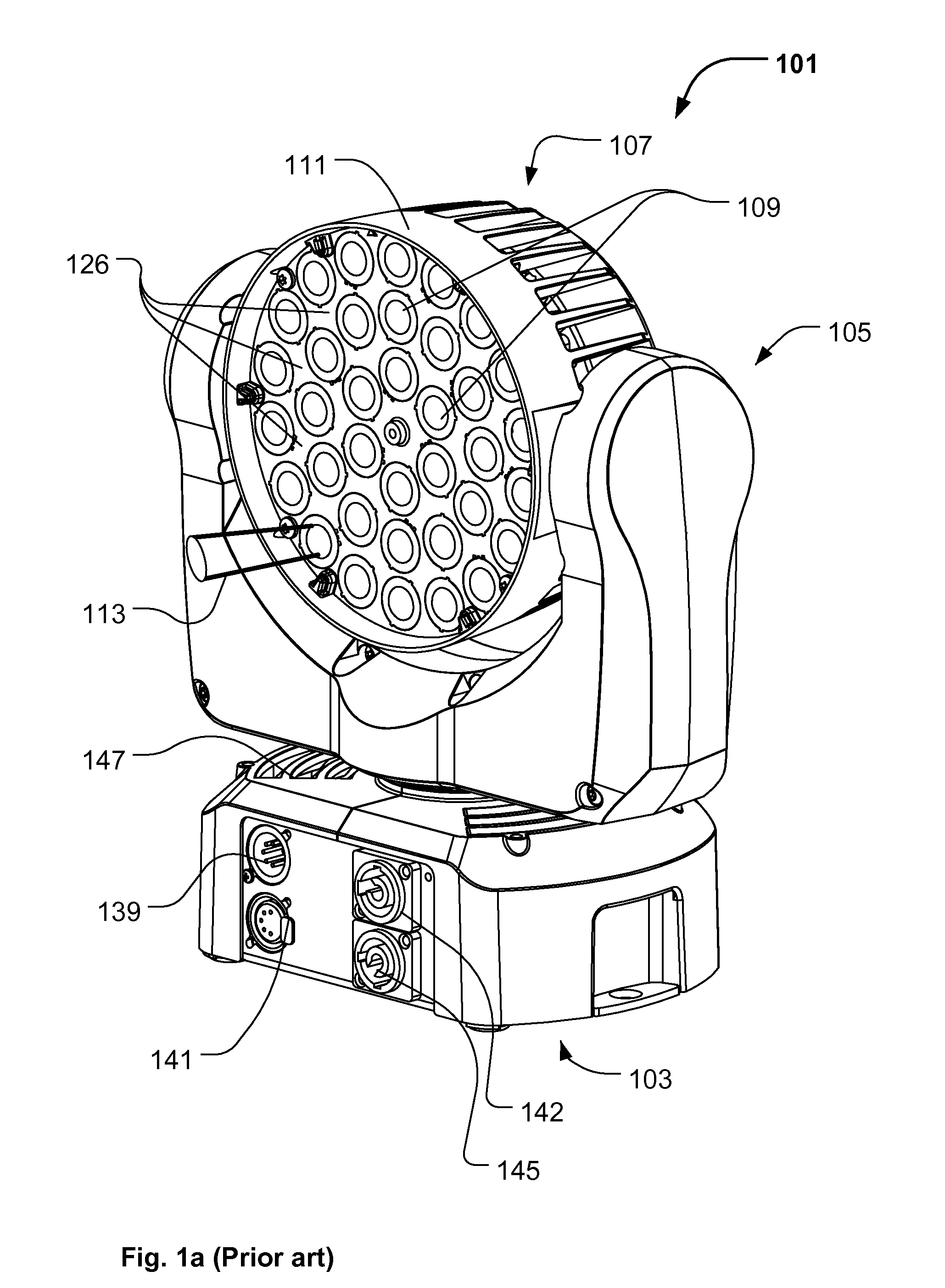
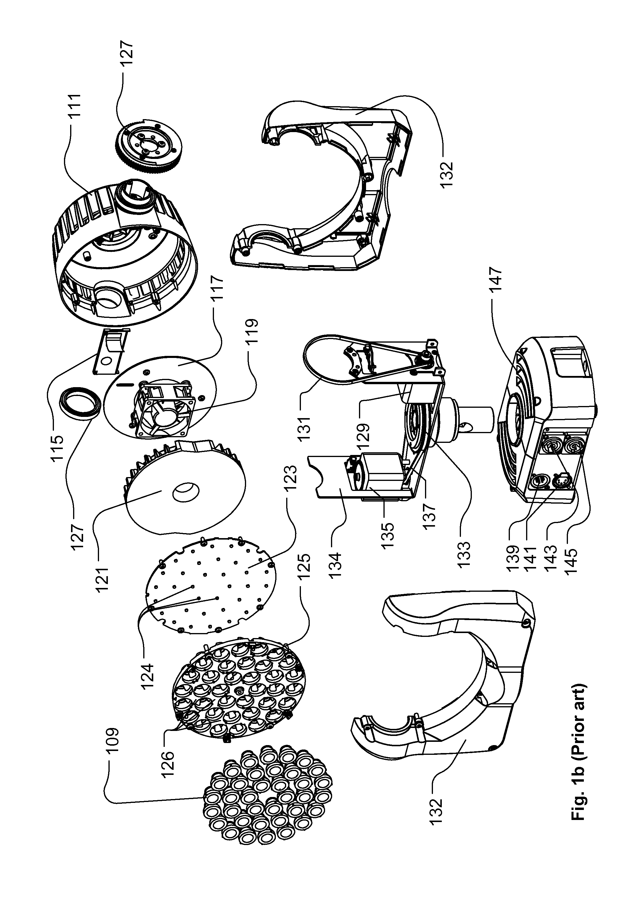
[0006]FIG. 1a and 1b illustrate an example of a moving head lighting fixture according to prior art;

[0007]FIG. 2a- 2c illustrate an embodiment of an illumination device according to the present invention;

[0008]FIG. 3a-3b illustrate the illumination device of FIG. 1a-1b modified into an illumination device according to the present invention;

[0009]FIG. 4a-4c illustrate another embodiment of an illumination device according the present invention;

[0010]FIG. 5 illustrates a block diagram of a illumination device according to the present invention.

DETAILED DESCRIPTION OF THE INVE...


PUM


Abstract

An illumination device with a number of light sources arranged in at least two groups of light sources that are individually controllable. The first group of light sources (203) have light collectors (209) such as internal reflection (TIR) lenses, mixers or other lenses placed over them to collect and convert light of the light sources into a number of light source beams. The second group of light sources (205) pass light through diffusing areas (215) of a diffuser (213) in the form of a diffusion cover included in the lamp housing to diffuse the light and create a background light for the first group of light sources. The light from the first group of light sources pass through non diffusing regions (211) of the diffuser cover without the light being diffused. The second group of light sources are interleaved with the first group by the diffuser having one or several diffusion areas between non diffusion areas. By controlling both groups of light sources based on the same target color the dotted look of led light sources can be removed or by controlling the two groups of light sources based on two different colors light effects can be obtained. The illumination device can be included in a moving head light source with a base, a yoke connected rotatably to the base and the head connected rotatably to the head.

Description

FIELD OF THE INVENTION[0001]The present invention relates to an illumination device comprising a number of light sources and a number of light collecting means arranged in a housing. The number of light collecting means collect light from at least one of the light sources and convert the collected into a number of source light beams and the light source beams are emitted from said housing.BACKGROUND OF THE INVENTION[0002]Light fixtures creating various effects are getting more and more used in the entertainment industry in order to create various light effects and mood lighting in connection with live shows, TV shows, sport events or as a part on architectural installation.[0003]Entertainment light fixtures creates typically a light beam having a beam width and a divergence and can for instance be wash / flood fixtures creating a relatively wide light beam with a uniform light distribution or it can be profile fixtures adapted to project an image onto a target surface. There is a tend...

Claims


Application Information

Patent Timeline
Patent Type & Authority Applications(United States)
IPC IPC(8): H05B39/04F21Y113/20H05B44/00
CPCF21S10/023F21Y2113/02F21V21/30F21W2131/406F21Y2101/02G02B5/0278G02B26/08H05B33/0803H05B33/0857F21Y2105/003F21V5/007F21Y2113/005F21V29/677F21V29/74F21V7/0083F21Y2105/10F21Y2105/12F21Y2113/13F21Y2113/20F21Y2115/10H05B45/20H05B45/00H05B45/325
Inventor VINTHER, THOMASHANSEN, CLAUS
Owner MARTIN PROFESSIONAL
Why Eureka
Try Eureka