Differential encoding using a 3D graphics processor

a technology of 3d graphics and encoding, applied in the field of differential encoding and decoding techniques, can solve the problems of limited processing power of the encoding system, computationally intensive motion estimation” processes, complex processes, etc., and achieve the effect of reducing the computational burden

Active Publication Date: 2012-04-19
ARM NORWAY
View PDF1 Cites 14 Cited by
  • Summary
  • Abstract
  • Description
  • Claims
  • Application Information

AI Technical Summary

Benefits of technology

[0040]In this way, the present invention provides a mechanism for using a 3D graphics rendering module (e.g. pipeline) to compare data of different graphics fragments that have the same position in a given two-dimensional block of fragments, i.e. for carrying out steps necessary for, for example, motion estimation for differential video encoding. This provides the ability to carry out the data comparison, necessary for, e.g. motion estimation, in hardware, which, as discussed above, is and can be advantageous.
[0216]As will be appreciated from the above, these aspects and arrangements of the present invention basically facilitate efficient, hardware-based addition and subtraction of 2-dimensional blocks of data by using an addition and / or subtraction circuit in a 3D graphics rendering module (e.g. pipeline) to add or subtract fragment data values in a memory buffer of the rendering module and data values of subsequently rendered graphics fragments.

Problems solved by technology

This process is complicated by the fact that, typically, the area of the “prediction” (reference) frame that most closely matches a given block or area in the current frame will not be in the same position within the reference frame as that area is in the current frame.
However, because they require a comparison between a large number of pixel video data values (e.g. 256 pixel values where 16×16 pixel blocks are being tested), such “motion estimation” processes are computationally intensive, even if the range of the search over the reference frame (i.e. the region of the reference frame over which the search for the closest matching frame area is carried out) is deliberately limited.
This can be disadvantageous generally, but particularly is so where the processing power of the encoding system may be limited.

Method used


Image

  • Differential encoding using a 3D graphics processor
  • Differential encoding using a 3D graphics processor
  • Differential encoding using a 3D graphics processor

Examples


Embodiment Construction

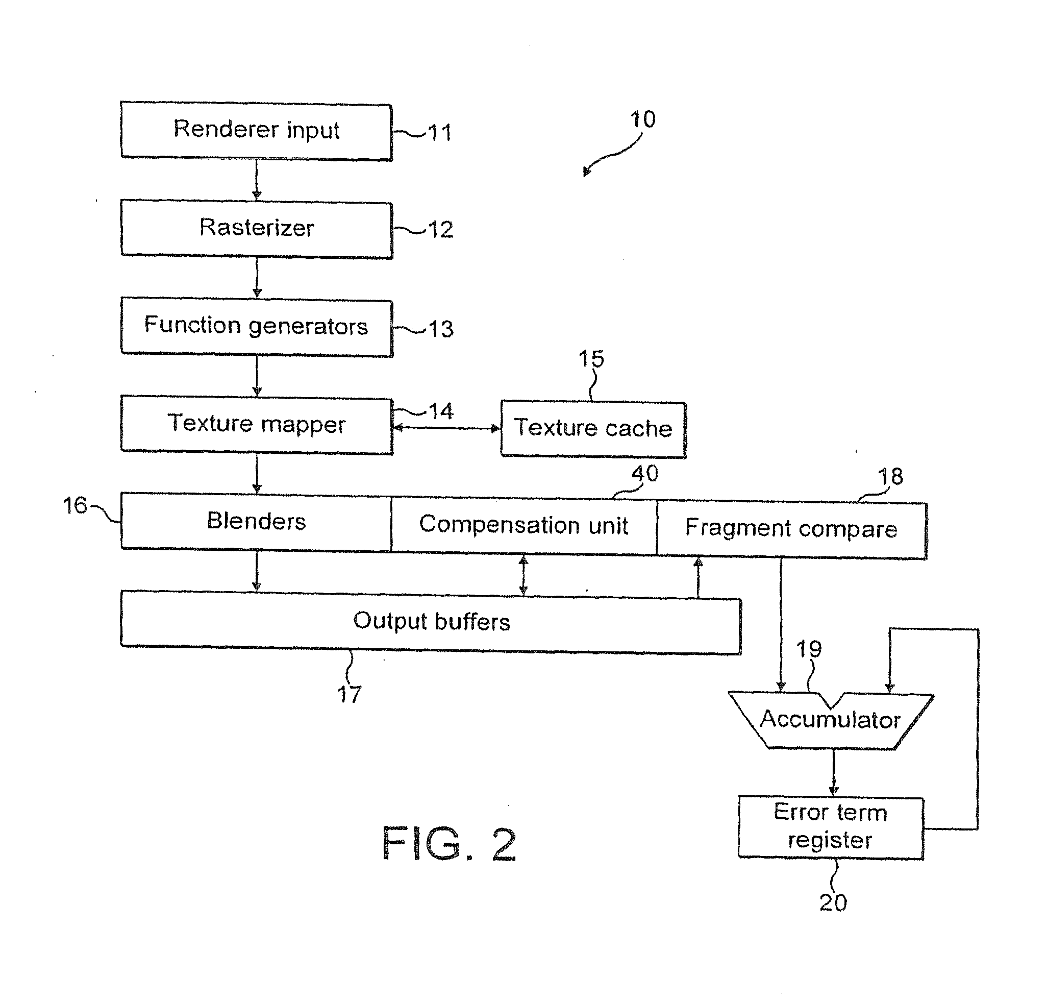
[0232]A preferred embodiment of the present invention for carrying out data operations necessary for motion estimation and compensation operations in MPEG video data compression and encoding will now be described.

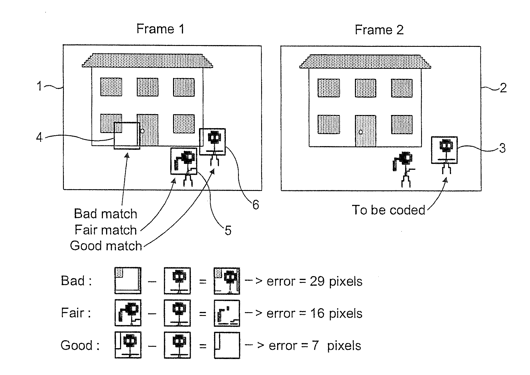
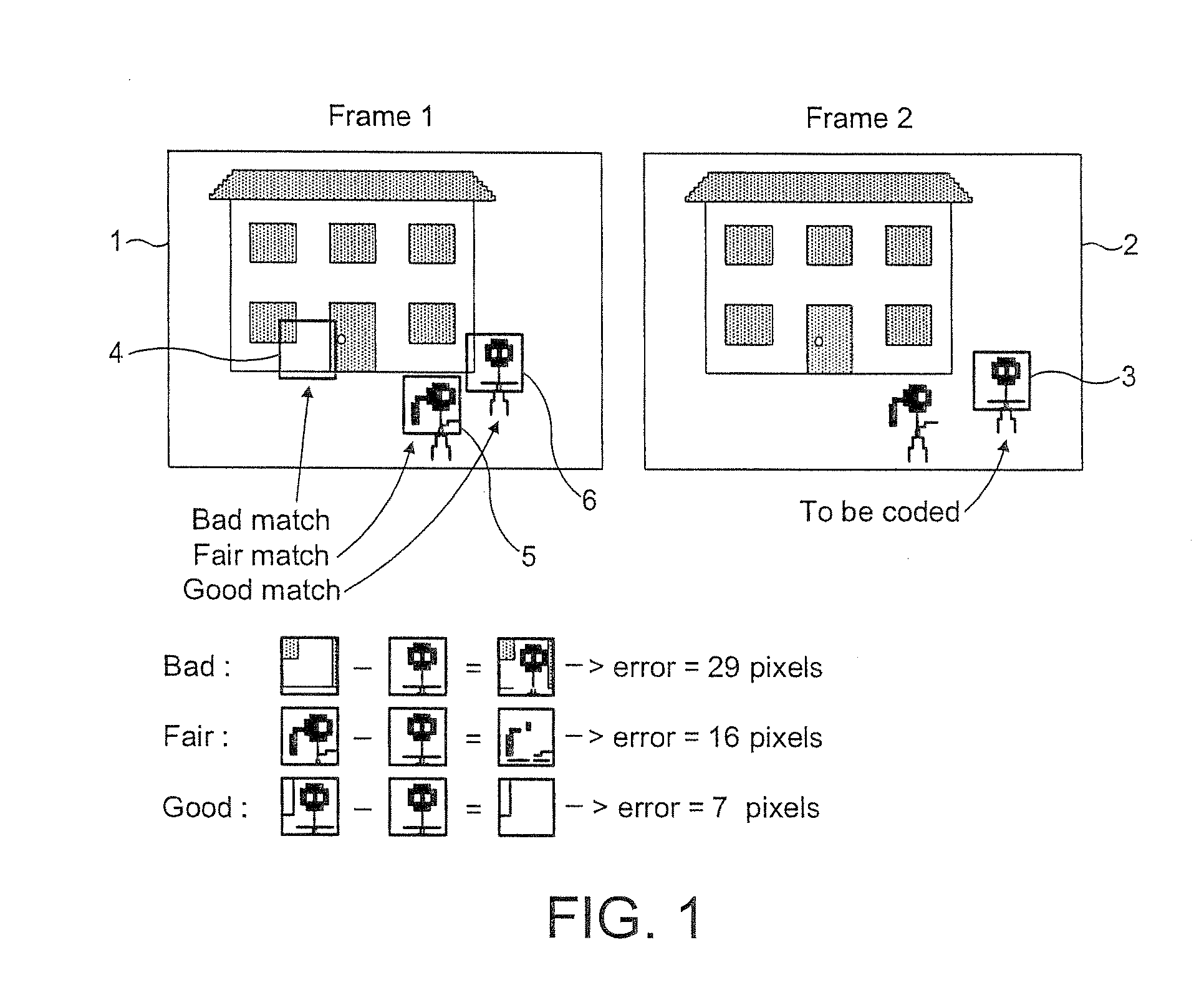
[0233]As is known in the art, an MPEG video stream comprises a series of video frames. Each video frame is divided into pixels (picture elements), and in order to be able to display the video frame, video data representing, for example, red, green and blue (RGB) colour values for each pixel in the frame is required. While it would be possible simply to store and handle the video data in RGB format, representing a series of video frames as RGB colour values requires a significant amount of data, and therefore it is known in the art to try to compress the source video data when it is, e.g., encoded for transmission, so as to reduce the amount of data that needs to be transmitted. A number of compression techniques are used for this purpose.

[0234]Firstly, the red-green-blue (R...


PUM


Abstract

A 3D graphics rendering pipeline is used to carry out data comparisons for motion estimation in video data encoding. Video data for the pixel block of the video frame currently being encoded is loaded into the output buffers of the rendering pipeline. The video data for the comparison pixel blocks from the reference video frame is stored as texture map values in the texture cache of the rendering pipeline. Once the sets of pixel data for comparison have been stored, the rendering pipeline is controlled to render a primitive having fragment positions and texture coordinates corresponding to the data values that it is desired to compare. As each fragment is rendered, the stored and rendered fragment data is compared by fragment compare unit and the determined differences in the data values are accumulated in an error term register.

Description

[0001]This application is a Continuation of application Ser. No. 10 / 569,345, filed Jan. 30, 2007, which is the US national phase of international application PCT / GB2004 / 003598, filed in English on Aug. 20, 2004, which designated the US. PCT / GB2004 / 003598 claims priority to GB Application No. 0319697.9 filed Aug. 21, 2003. The entire contents of these applications are incorporated herein by reference.BACKGROUND OF THE INVENTION[0002]1. Field of the Invention[0003]The present invention relates to a method and an apparatus suitable for use with differential encoding and decoding techniques, and in particular to such a method and apparatus suitable for use with video compression encoding and decoding techniques.[0004]2. Discussion of Prior Art[0005]As is known in the art, differential encoding involves comparing portions of data with one another and using information relating to the differences between the portions of data rather than the entire data portions themselves to represent the...

Claims


Application Information

Patent Timeline
Patent Type & Authority Applications(United States)
IPC IPC(8): H04N13/00G06T7/20H04N5/14H04N7/26
CPCH04N19/43G06T7/223H04N5/144
Inventor NYSTAD, JORNSORGARD, EDVARDLJOSLAND, BORGARBLAZEVIC, MARIO
Owner ARM NORWAY
Why Eureka
Try Eureka