Separate igniter fuel injection system

Inactive Publication Date: 2012-04-26
FIREY JOSEPH CARL
View PDF4 Cites 5 Cited by
  • Summary
  • Abstract
  • Description
  • Claims
  • Application Information

AI Technical Summary

Benefits of technology

[0026]The improvement invention described herein is a combination of a separate igniter fuel injection system, added on to a diesel engine, equipped with a common rail slurry fuel injection system. The common rail slurry fuel injection system utilizes a combined double valve slurry fuel injector, operated by a hydraulic fluid common rail, separate from the slurry fuel common rail, as described in my earlier filed U.S. patent application entitled, Common Rail Slurry Fuel Injection System, Ser. No. 12/799,209, filed 21 Apr. 2010. A small quantity of a volatile, high cetane number igniter fuel is injected, via this separate igniter fuel injection system into the engine combustion chambers, during each engine compression stroke, and prior to the injection of the ta

Problems solved by technology

The early compression ignition of the small portion of igniter fuel creates high temperature gas and pressure waves, which promote rapid fuel evaporation and th

Method used


Image

  • Separate igniter fuel injection system
  • Separate igniter fuel injection system
  • Separate igniter fuel injection system

Examples


Embodiment Construction

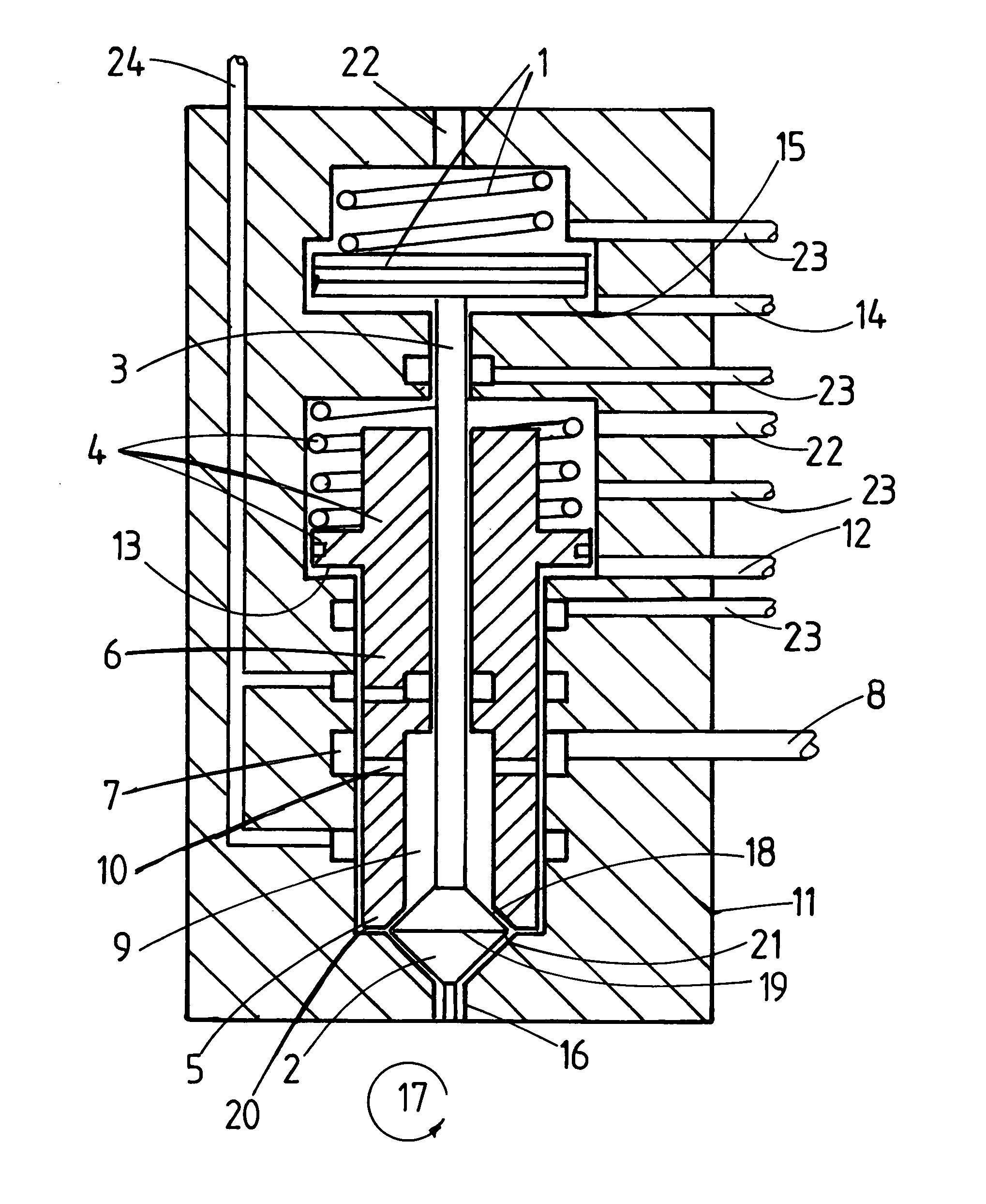
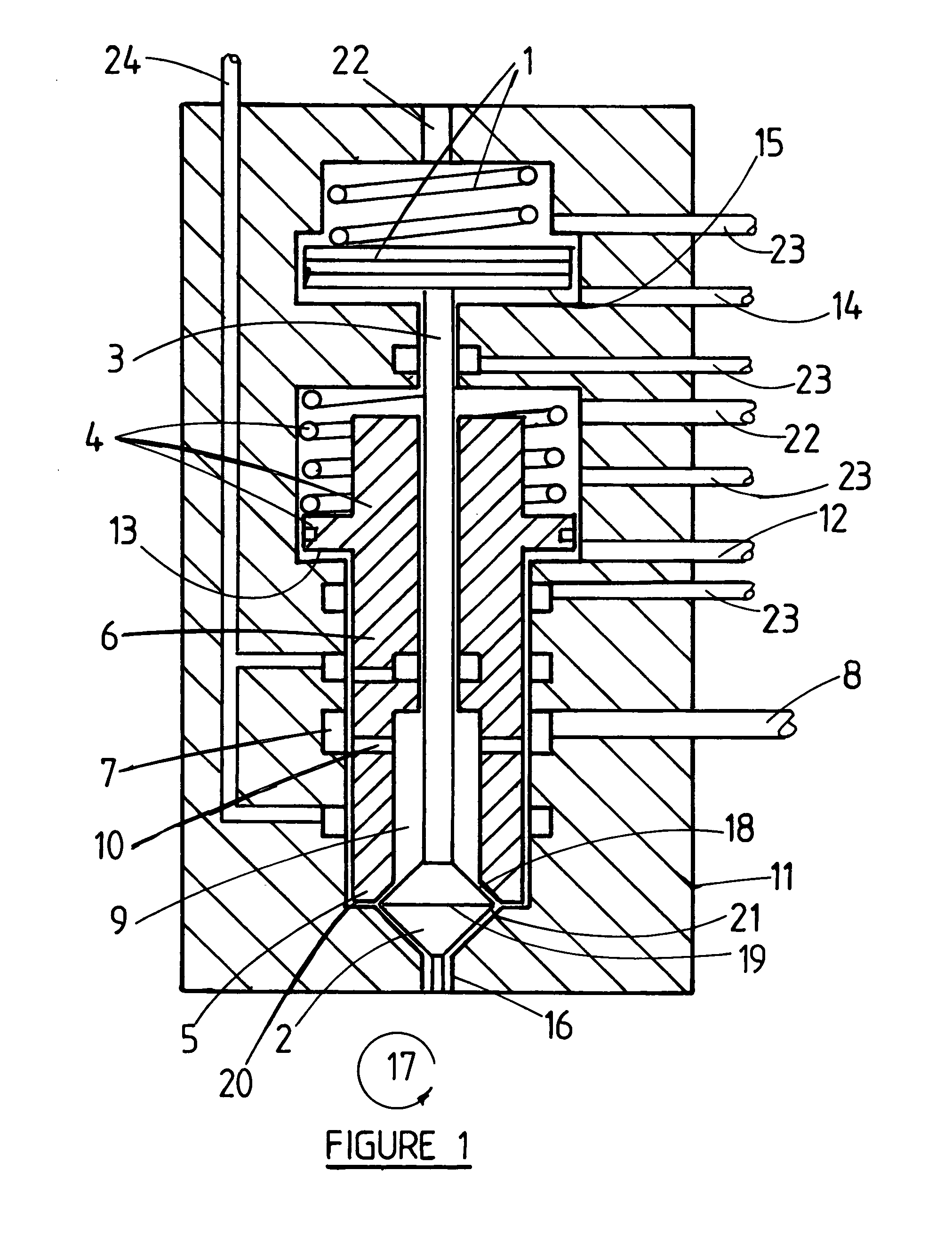
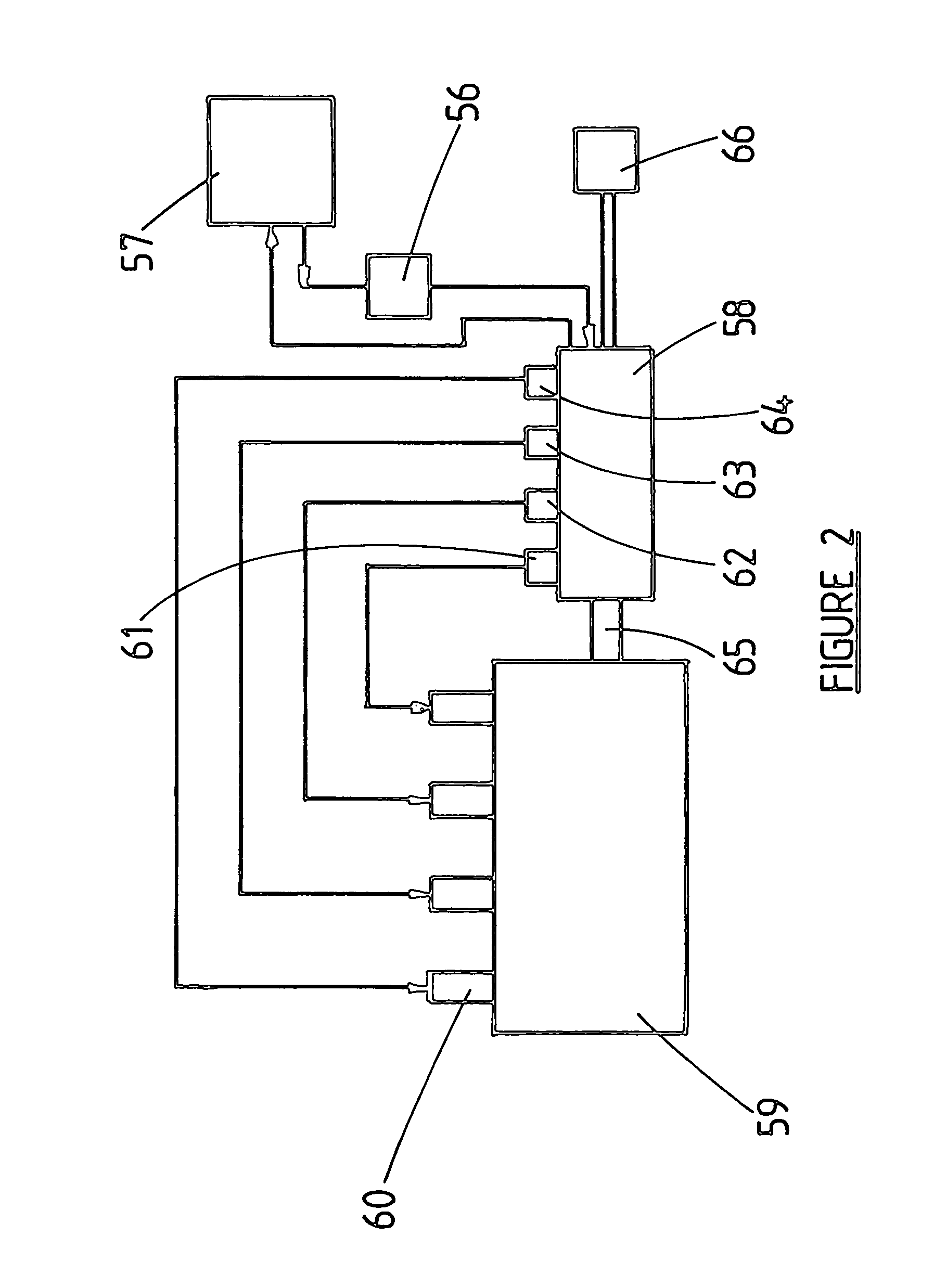
[0038]All forms of the invention described herein are an improvement on the invention described in my earlier filed US patent application entitled, Common Rail Slurry Fuel Injection System, Ser. No. 12 / 799,209, filed 21 Apr. 2010, and this material is incorporated herein by reference thereto. The improvement comprises adding to the engine a separate igniter fuel injection system, which injects a small quantity of a high cetane number igniter fuel, into each engine combustion chamber, driving each piston compression stroke, and prior to the engine of a larger quantity of slurry fuel thereinto by the Common Rail Slurry Fuel Injection System referred to above. Compression ignition and burning of this small igniter fuel quantity supplies hot gas, and pressure waves, to promote the subsequent evaporation and thermal cracking of the tar-like fuel particles from the slurry fuel. In this way the combustion of the slurry fuel is more rapid and more complete, with resulting improvement in eng...


PUM


Abstract

A separate igniter fuel injection system is described for use with diesel engines operating on tar based slurry fuel with a common rail slurry fuel injection system. The igniter fuel is injected prior to injection of the slurry fuel, during each engine compression stroke, so that the ignition and burning of the igniter fuel will supply hot gases for the evaporation and thermal cracking needed to ignite the tar fuel portions of the slurry. This separate igniter fuel injection system can also be used for cold startup of a diesel engine operated on tar based slurry fuels.

Description

CROSS REFERENCES TO RELATED PATENTS AND APPLICATIONS[0001]The invention described herein is related to my following US patent applications:[0002](1) U.S. Pat. No. 6,444,000, entitled, Steam Driven Fuel Slurrifier, issued 8 Sep. 2002.[0003](2) U.S. Pat. No. 7,677,791, entitled, Rotary Residual Fuel Slurrifier, issued 16 Mar. 2010.[0004](3) U.S. patent application Ser. No. 12 / 583,448, entitled, Rotary Tar Slurrifier, filed 21 Aug. 2009.[0005]The above patents and applications describe apparatus for preatomizing high viscosity tars and residual fuels.[0006](4) U.S. Pat. No. 7,281,500, entitled, Supplementary Slurry Fuel Atomizer and Supply System, issued 16 Oct. 2007.[0007](5) U.S. Pat. No. 7,418,927, entitled, Common Rail Supplementary Atomizer for Piston Engines, issued 2 Sep. 2008.[0008](6) U.S. patent application Ser. No. 12 / 011,569, entitled, Modified Common Rail Fuel Injection System, filed 19 Jan. 2008.[0009]The above patents and applications describe the use of contactor chambe...

Claims


Application Information

Patent Timeline
IPC IPC(8): F02M43/04
CPCF02M43/04
Inventor FIREY, JOSEPH CARL
Owner FIREY JOSEPH CARL
Why Eureka
Try Eureka