Wireless charging method and apparatus

Active Publication Date: 2012-04-26
SAMSUNG ELECTRONICS CO LTD
View PDF5 Cites 268 Cited by
  • Summary
  • Abstract
  • Description
  • Claims
  • Application Information

AI Technical Summary

Benefits of technology

[0017]In accordance with the present invention, there is provided a wireless charging method including synchronizing power phases of at least two charging power supply devices, and wirelessly charging a terminal using the at least two charging power supply devices.

Problems solved by technology

This contact-type charging scheme may often undergo contamination by foreign substances, such as moisture, causing incorrect battery charging, because the contact terminals protrude outward.

Method used


Image

  • Wireless charging method and apparatus
  • Wireless charging method and apparatus
  • Wireless charging method and apparatus

Examples


Embodiment Construction

[0032]Embodiments of the present invention will now be described in detail with reference to the accompanying drawings. In the following description, specific details such as detailed configuration and components are merely provided to assist the overall understanding of embodiments of the present invention. Therefore, it should be apparent to those skilled in the art that various changes and modifications of the embodiments described herein can be made without departing from the scope and spirit of the invention. In addition, descriptions of well-known functions and constructions are omitted for the sake of clarity and conciseness.

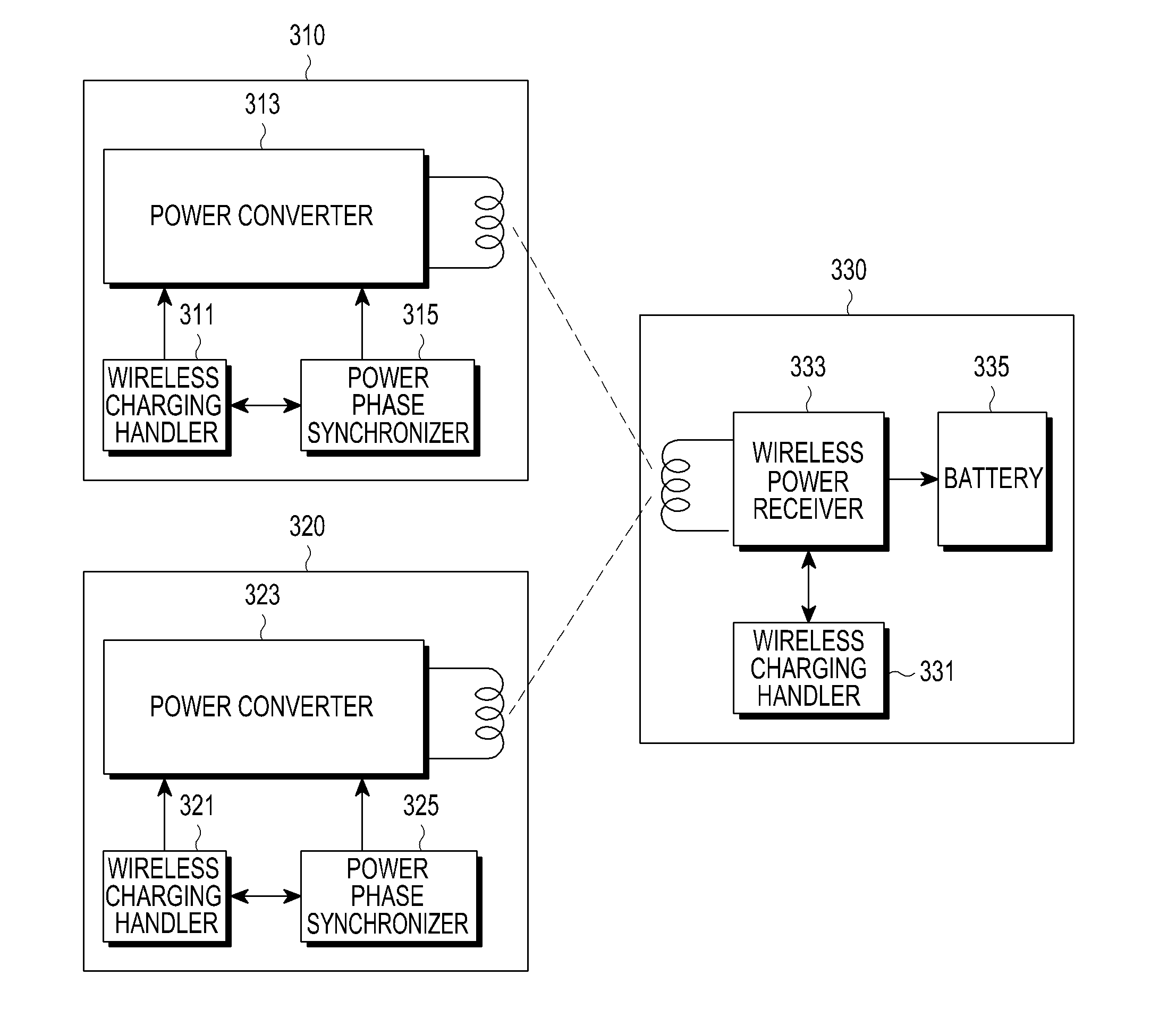
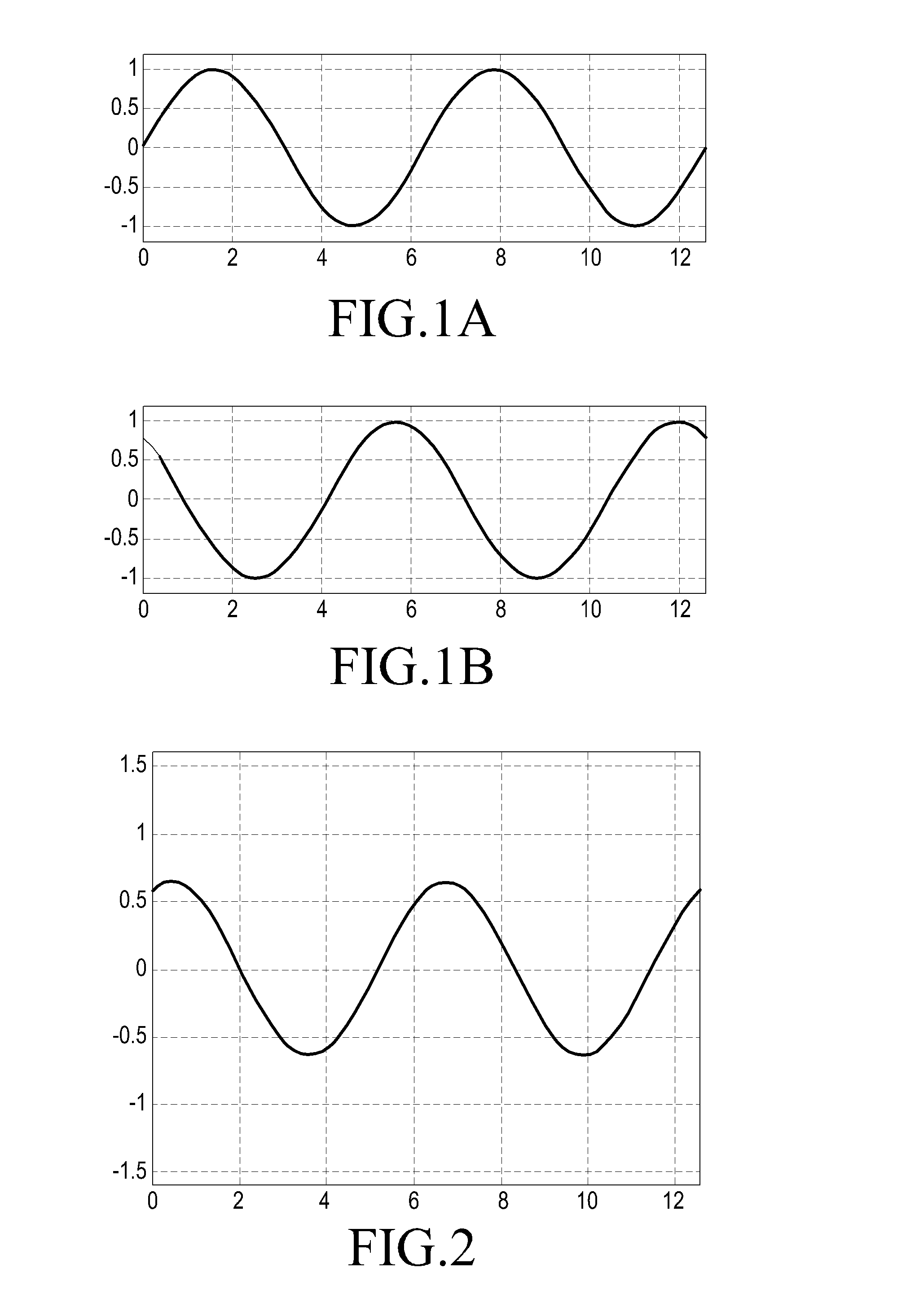
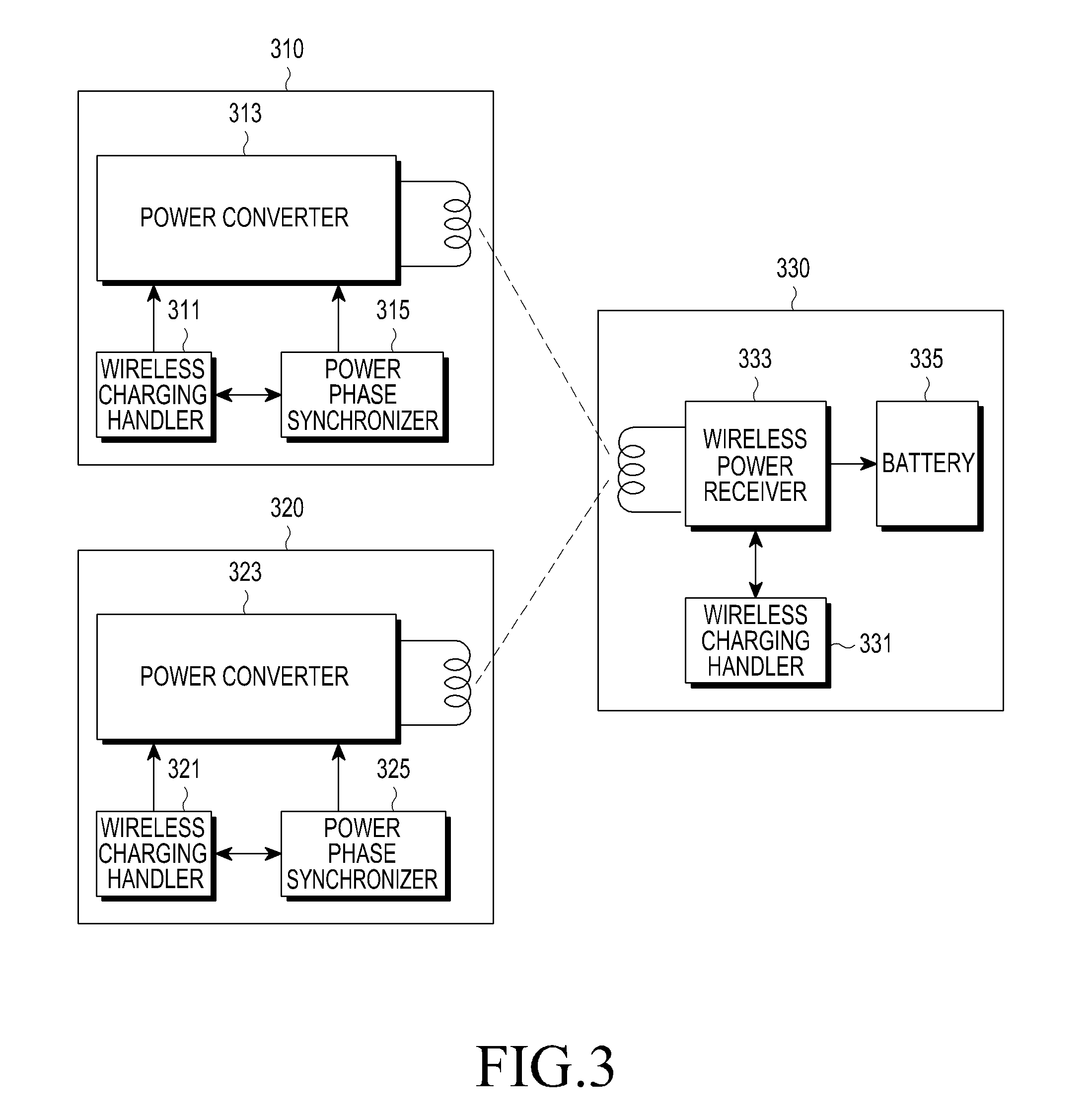
[0033]When a plurality of charging power supply devices simultaneously transmit their charging power to at least one terminal, the power transmitted by the plurality of charging power supply devices may have different phase characteristics, drastically reducing the power transmission efficiency. Specifically, assume that first and second charging power su...


PUM


Abstract

A wireless charging method includes synchronizing power phases of at least two charging power supply devices, and wirelessly charging a terminal using the at least two charging power supply devices.

Description

PRIORITY[0001]This application claims priority under 35 U.S.C. §119(a) to a Korean Patent Application filed in the Korean Intellectual Property Office on Oct. 21, 2010 and assigned Serial No. 10-2010-0103170, the contents of which are incorporated herein by reference.BACKGROUND OF THE INVENTION[0002]1. Field of the Invention[0003]The present invention relates generally to a charging method and apparatus, and more particularly, to a method and apparatus for performing wireless charging.[0004]2. Description of the Related Art[0005]A mobile terminal, such as a cell phone or a Personal Digital Assistant (PDA), is generally powered by a rechargeable battery that is recharged by electrical energy from a separate charging device. The charging device and the battery have their own separate external contact terminals, and are electrically connected by mechanically connecting the contact terminals to each other.[0006]This contact-type charging scheme may often undergo contamination by foreign...

Claims


Application Information

Patent Timeline
IPC IPC(8): H02J7/00
CPCH02J5/005H02J7/025H02J50/80H02J7/00034H02J50/40H02J50/10H02J50/90H04B5/79
Inventor KANG, NOH-GYOUNGWON, EUN-TAEPARK, JOON-HOKOH, JUN-HOPARK, SE-HOJUNG, HEE-WON
Owner SAMSUNG ELECTRONICS CO LTD
Why Eureka
Try Eureka