Leverage device for hand tools

a technology of hand tools and levers, which is applied in the field of levers for hand tools, can solve the problems of time-consuming and time-consuming tasks, many implements are vulnerable to inconsistent production, and it is difficult to use any of these tools, so as to achieve a greater range of use of tools, improve the use efficiency, and improve the effect of operation speed

Inactive Publication Date: 2012-05-10
KIMBALL KIM S
View PDF17 Cites 3 Cited by
  • Summary
  • Abstract
  • Description
  • Claims
  • Application Information

AI Technical Summary

Benefits of technology

[0018]The preferred embodiment also produces a remarkable ability to use a hand tool in a smooth, fluid motion. This is accomplished with its outboard stabilizing system consisting of the outboard rollers, wheels, or the like, thus providing a balanced, stabilized operation with the tool's head. This natural balance allows a smooth movement back and forth of the tool being used, which movement would otherwise be difficult or impractical at best. Unlike prior art the work head can efficiently and practically be used in both the forward and backward direction giving a greater range use of the tool. Likewise, it makes the task of many everyday operations much easier for the user with a more consistent outcome.
[0019]While simple rods or braces alone can create a desired leverage contact point for stability, it would be more desirable to use rollers or wheels as will be subsequently illustrated herein. With movable outboard points such as wheels, rollers and skids, the desirable back and forth movement of the tool is easier, faster and smoother to operate.

Problems solved by technology

Many implements are also vulnerable to producing inconsistent results.
It is difficult to use any of these tools and produce a consistent outcome, unless the user is particularly skilled in its use, and even then it is a time consuming task that requires much redo.
Other factors that affect consistent results is that these tools are vulnerable to the user tiring, and may become difficult to use, unstable even, as they may bounce or bump over an even or uneven surface.
Even the use of a squeegee can be challenging at times, trying to drag its rubber blade over large windows, glass doors or flooring surfaces.
Uneven draws of the squeegee are commonplace and at times tiring not knowing if pressure is being applied evenly.
There are several problems with this type of hand cultivator, the first of which is its stability, or instability, as the case may be.
Second is control, or lack thereof, as the case may be, since it does not function from a stable platform having only two points of contact with the soil (ground).
Third, the cultivator is unidirectional and is incapable of moving back and forth.
Fourth, it lacks adaptability or versatility of use for any other applications as it is specifically designed only for a row garden.
The difficulty of use of all of these prior art manually pushed or pulled implements is directly related to the lack of being able to provide proper pressure, or leverage as the case may be.
Obviously the physical restrictions, substantial space requirements, environmental concerns, and high costs, would make the motorized approach impractical for most gardens and backyards.

Method used


Image

  • Leverage device for hand tools
  • Leverage device for hand tools
  • Leverage device for hand tools

Examples


embodiment 50

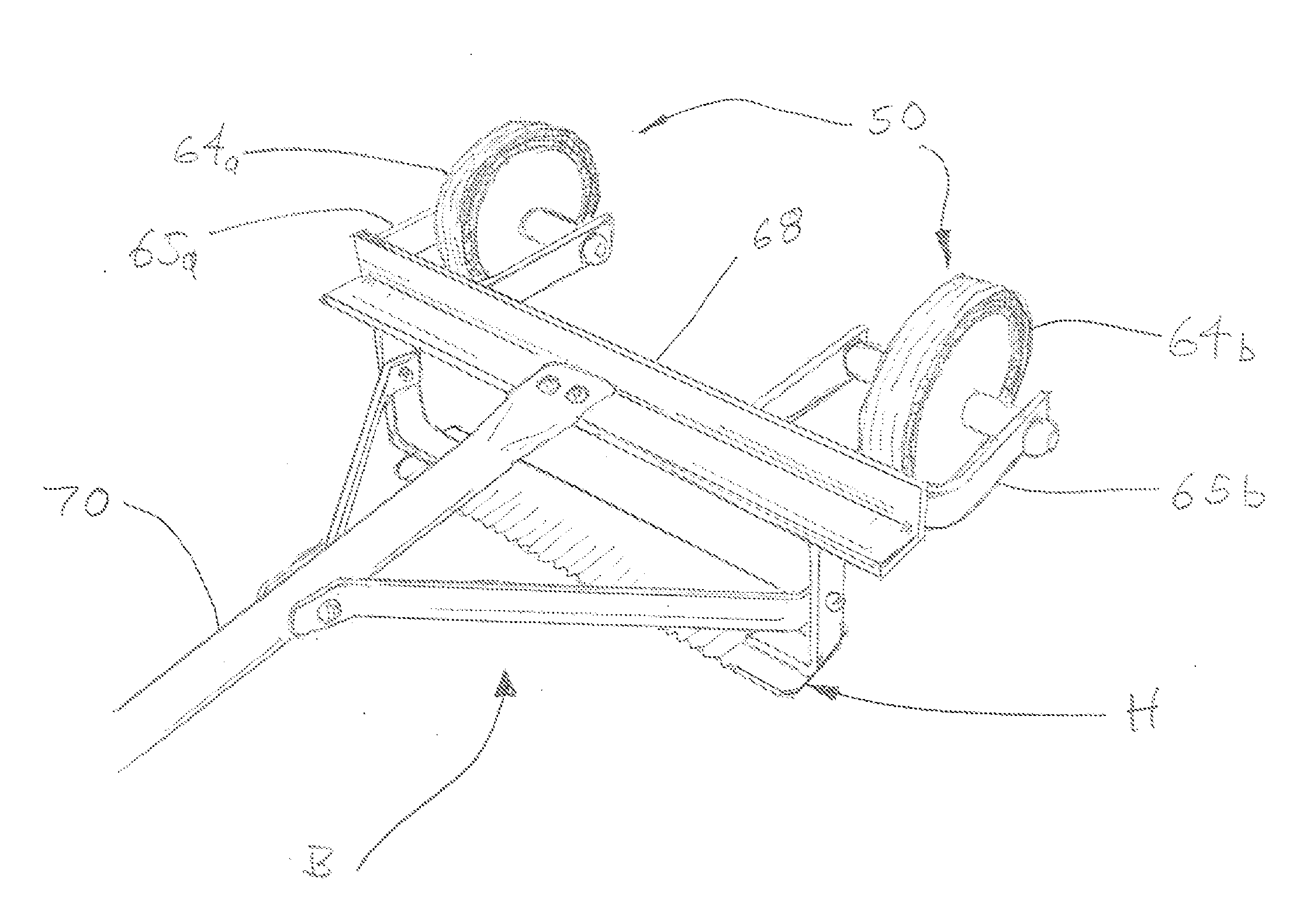
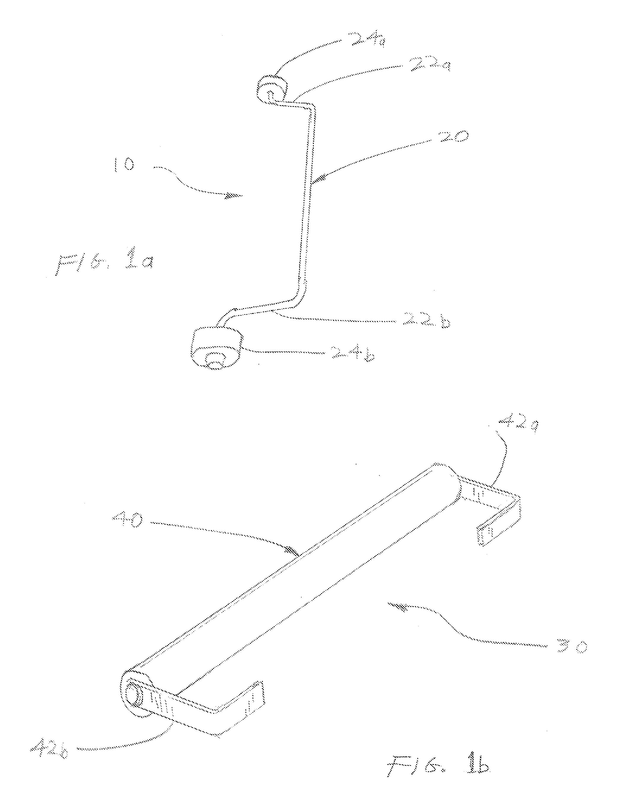
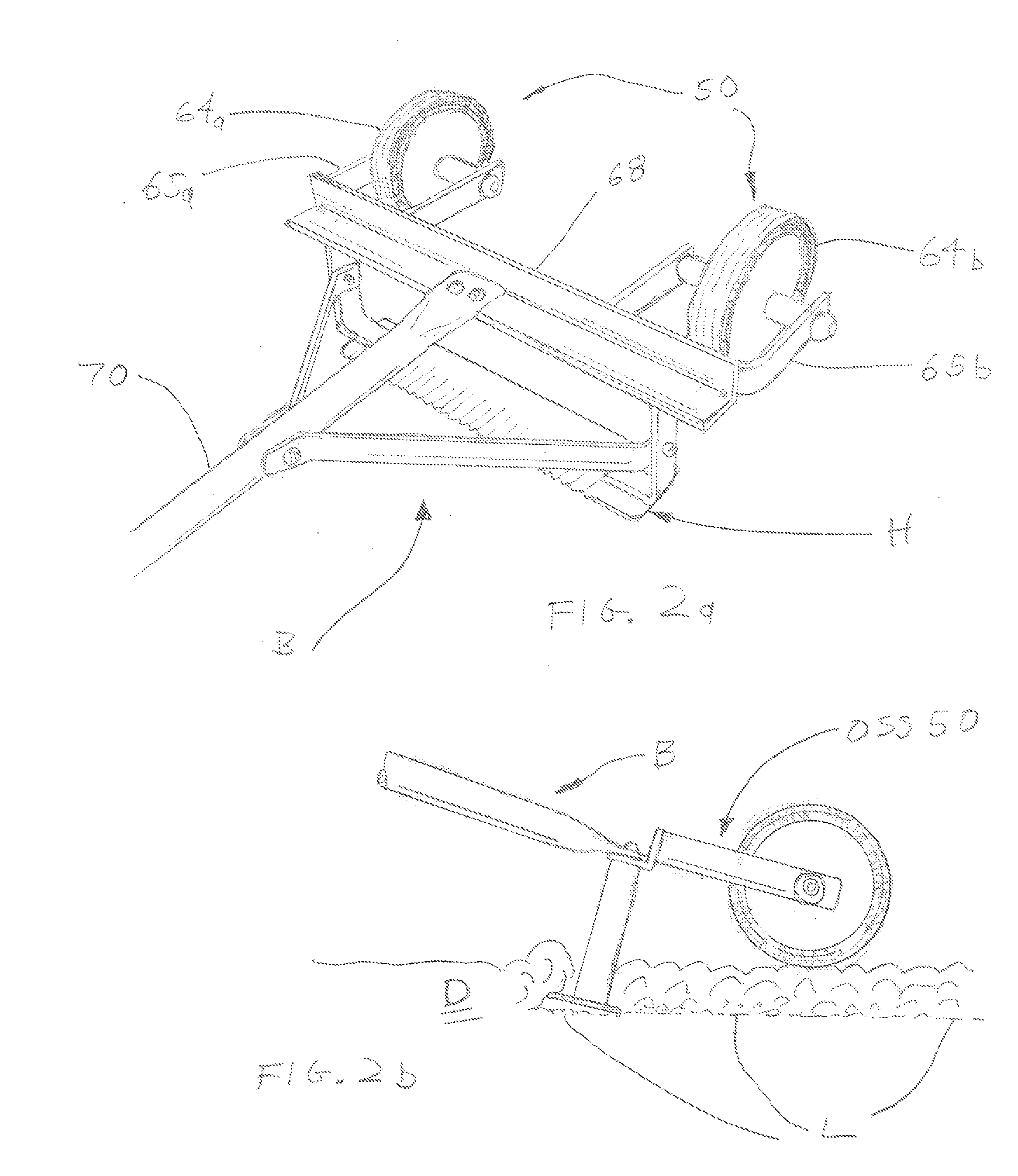
[0050]In FIG. 2a, the preferred embodiment 50, much like that of OSS 10 in FIG. 1a, but with two larger wheels 64a and 64b, attached by two large U-shaped brackets 65a and 65b, in turn said brackets are attached to cross member 68, which in turn is attached to handle 70 of hoe B. Head assembly H of hoe B is like any common variety of hoe used for upturning soil when preparing for planting, or as may be used for de-weeding and so on. As illustrated, OSS 50 is in an outboard location several inches behind hoe E. This distance may vary depending on the type or size of tool being used and the application. In most relatively common uses and applications, the distance would be about 4″ to 7″ out from the cross member 68.

[0051]In FIG. 2a hoe B with the preferred embodiment OSS 50 attached, is able to easily upturn dirt D and at a consistent depth shown as line L. With OSS 50 hoe B has several substantial advantages. First, it maintains an even drawing when the user (not shown) pulls on hoe...

embodiment 30

[0052]In this particular application with the use on a hoe, the type of OSS used, either with wheels as illustrated or like the preferred embodiment 30 in FIG. 1b, the outcome is feasible, but the larger wheels in OSS 50 make it easier.

[0053]In FIG. 3a, the preferred embodiment 30 in FIG. 1b has been attached to a garden rake R. As illustrated, the two outboard extensions 42a and 42b have been attached to rake R by fasteners 46a and 46b, thus placing stabilizer roller 40 outboard (outward) from rake head H. As illustrated the distance between stabilizer roller 40 and rake head H may depend on the type of rake being used and the application. In most relatively common garden uses and applications with a rake, the distance would be about 3″ to 5″ outward from tines T in rake head H.

[0054]In FIG. 3a rake R with the preferred embodiment OSS 30 attached is able to rake a surface S with several substantial advantages. First, it maintains an even drawing when the user (not shown) pulls on r...

embodiment 10

[0055]While it may be acceptable to use an OSS with wheels such as the preferred embodiment 10 illustrated in FIG. 1a, there is another particularly unique advantage of using OSS 30 with roller 40 as illustrated in FIGS. 3a and 3b. As illustrated in FIG. 3b stabilizer roller 40 serves not only serves as a stabilizer or a leverage device during raking, it also provides a grading function that smoothes down surface S after the raking when using the pulling process. In FIG. 3b this is more precisely illustrated with the un-raked surface U in a jagged line, raked surface V in a slightly jagged line, and with raked and smoothed surface W with a smooth liner.

[0056]In FIG. 4 grader G has an OSS 30 much like that in FIG. 1b and as used on rake R in FIGS. 3a and 3b. Grader G has one single blade B that spans the grader's entire width and is used to level out dirt, sand, gravel and the like in places such as walkways, paths, playgrounds, sports fields and so on. Stabilizer roller 40 sets outb...


PUM


Abstract

An outboard stabilizing system (OSS) includes a stabilizer bar with first and second outboard extensions each with a wheel mounted thereon; and a hand tool secured to the stabilizer bar, wherein a length of the two outboard extensions is determined based on the hand tool.

Description

[0001]The present application claims priority to Provisional Application Ser. No. 61 / 456,461, filed Nov. 8, 2010, the contents of which are incorporated by reference.BACKGROUND OF THE INVENTION[0002]The preferred embodiment relates generally to a leverage device for hand tools.DESCRIPTION OF PRIOR ART[0003]There are many common tools and implements that are typically handled such as garden implements like rakes, hoes, and graders, construction implements such as screeds and push brooms, and household implements such as squeegees or brushes.[0004]These implements usually use a pulling or pushing motion to operate. These tools when put to use all have a certain resistance based on the type of tool attached to its end. For example, the friction of the tines on a rake when being dragged over soil or a ground surface, provide fairly substantial resistance. A push broom drags thousands of bristles over a concrete floor and a hand grader drags its lateral blade atop soil also creating a fa...

Claims


Application Information

Patent Timeline
Patent Type & Authority Applications(United States)
IPC IPC(8): A01B15/12
CPCA01B1/00
Inventor KIMBALL, KIM S.
Owner KIMBALL KIM S
Why Eureka
Try Eureka