Strain sensor

a technology of bending sensor and sensor, which is applied in the direction of mechanical measuring arrangement, instruments, force/torque/work measurement apparatus, etc., can solve the problems of sensor signal reliability degradation, sensor unsuitable for automated mounting and integration in a production-line environment, and adhesive subject matter, etc., to achieve strong and stable bending response

a technology of bending sensor and sensor, which is applied in the direction of mechanical measuring arrangement, instruments, force/torque/work measurement apparatus, etc., can solve the problems of sensor signal reliability degradation, sensor unsuitable for automated mounting and integration in a production-line environment, and adhesive subject matter, etc., to achieve strong and stable bending response

US20120118070A1Inactive Publication Date: 2012-05-17AB SKF

Image

  • Strain sensor
  • Strain sensor
  • Strain sensor

Examples


Embodiment Construction

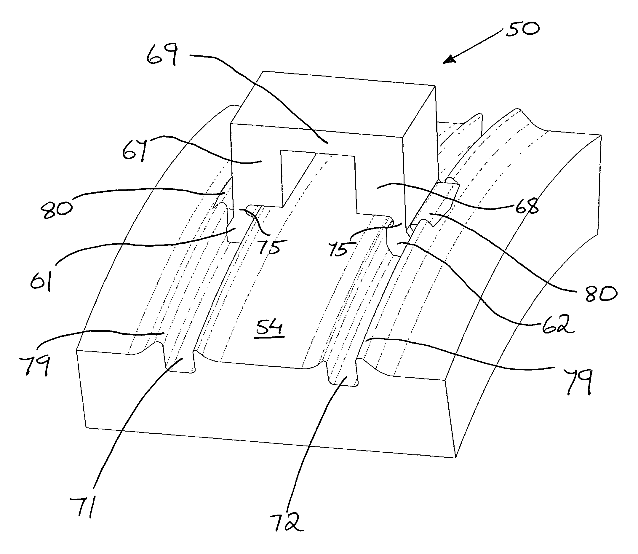
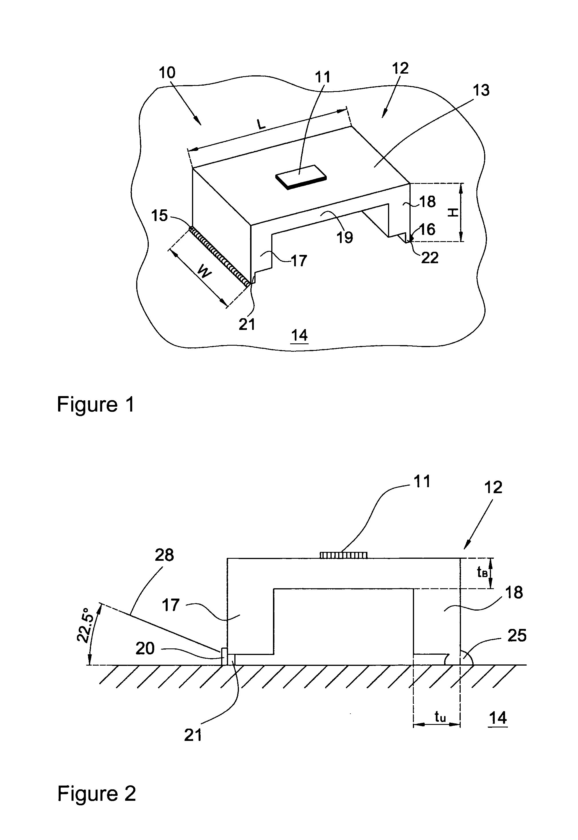
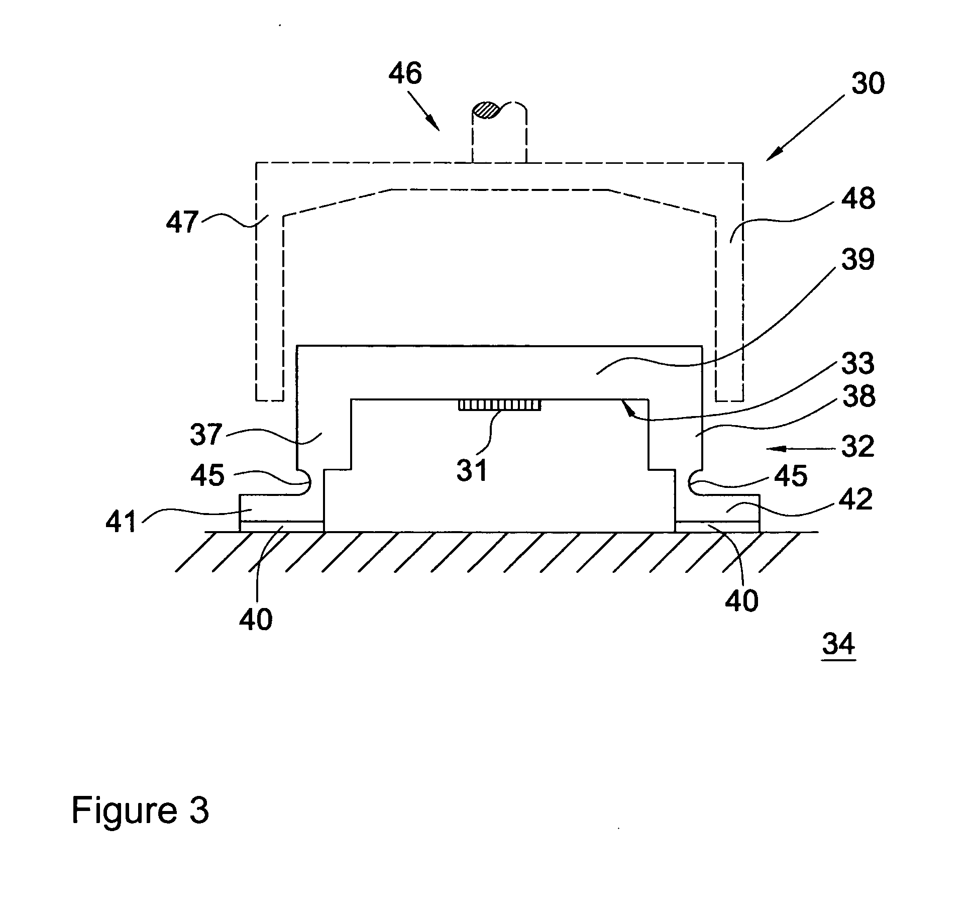
[0032]When there is a need to measure the loads acting on a rotationally supported component, one way of accomplishing this is to measure deformation of a bearing ring in a bearing that is used to support the component. The loads cause the bearing ring to deform, which deformation can be measured by attaching one or more strain sensors to a surface of the bearing ring, e.g. an outer circumference of the bearing outer ring. Strain sensors, such as plastic-foil strain gauges, can be adhesively bonded to the bearing surface, but adhesive bonding is a time-consuming process that is usually carried out manually. A further drawback is that over time, the adhesive can be subject to creep, which impairs the reliability of the strain signal over time. Metal-foil strain gauges can also be applied, whereby the perimeter of the metal foil gauge is welded to the bearing surface using a specific pattern of spot welds. Thus, the spot welding process is relatively time-consuming and complex. Foil s...


PUM


Abstract

The present invention defines a strain sensor for measuring strains induced on a component surface (34). The strain sensor comprises a strain gauge (31) and a support member (32), whereby the support member is attached to the component surface only at first and second attachment places. The support member comprises a beam portion (39) that is adapted to bend in response to a relative displacement of the first and second attachment places, and the strain gauge is integrated on a surface (33) of this beam portion. To ensure a strong and stable bending response of the beam portion, the attached support member comprises at least one flexure hinge (45).

Description

TECHNICAL FIELD[0001]The present invention concerns a strain sensor for measuring strains induced on a component surface, particularly a surface of a rolling element bearing. The present invention also concerns a method of attaching a strain sensor to a component surface, particularly a bearing surface, by means of a heat joining process.BACKGROUND WITH STATE OF ART[0002]Bearings are devices that permit constrained relative motion between two parts. They may be used in many different types of machinery to retain and support rotating components such as, for example, a wheel on a vehicle, a vane on a windmill or a drum in a washing machine. A typical bearing comprises inner and outer rings and a plurality of rolling elements, and may further comprise a cage to retain the rolling elements. During use, the bearing is subjected to different loads, both static and dynamic. The static load is mainly due to the weight supported by the bearing and may also be due to a preload with which the ...

Claims


Application Information

Patent Timeline
17 May 2012
Publication
US20120118070A1
IPC
G01B5/30
CPC
G01B7/20; G01L5/0019; G01G3/1412; G01G3/14
Inventors
MOL, HENDRIK ANNE; VAN DE SANDEN, JOHN