Cover locking device for portable terminal

Active Publication Date: 2012-05-17
SAMSUNG ELECTRONICS CO LTD
View PDF11 Cites 5 Cited by
  • Summary
  • Abstract
  • Description
  • Claims
  • Application Information

AI Technical Summary

Benefits of technology

[0012]Accordingly, the present invention has been made to solve the above-mentioned problems occurring in the prior art and provides additional advantages, by providing a cover locking device for a portable

Problems solved by technology

However, as shown in FIG. 1, the conventional locking device has a problem in that the cover 114 (“A” area) is exposed to the outside during lock and release modes which deteriorates the external appearance of the portable terminal.
Moreover, since above conventional cover locking device has a configuration allowing its protrusion to be entirely exposed to the exterior, t

Method used


Image

  • Cover locking device for portable terminal
  • Cover locking device for portable terminal
  • Cover locking device for portable terminal

Examples


Embodiment Construction

[0031]Hereinafter, embodiments of the present invention will be described with reference to the accompanying drawings. For the purpose of clarity and simplicity, the same elements will be designated by the same reference numerals although they are shown in different drawings.

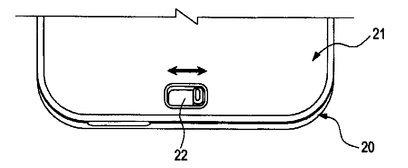
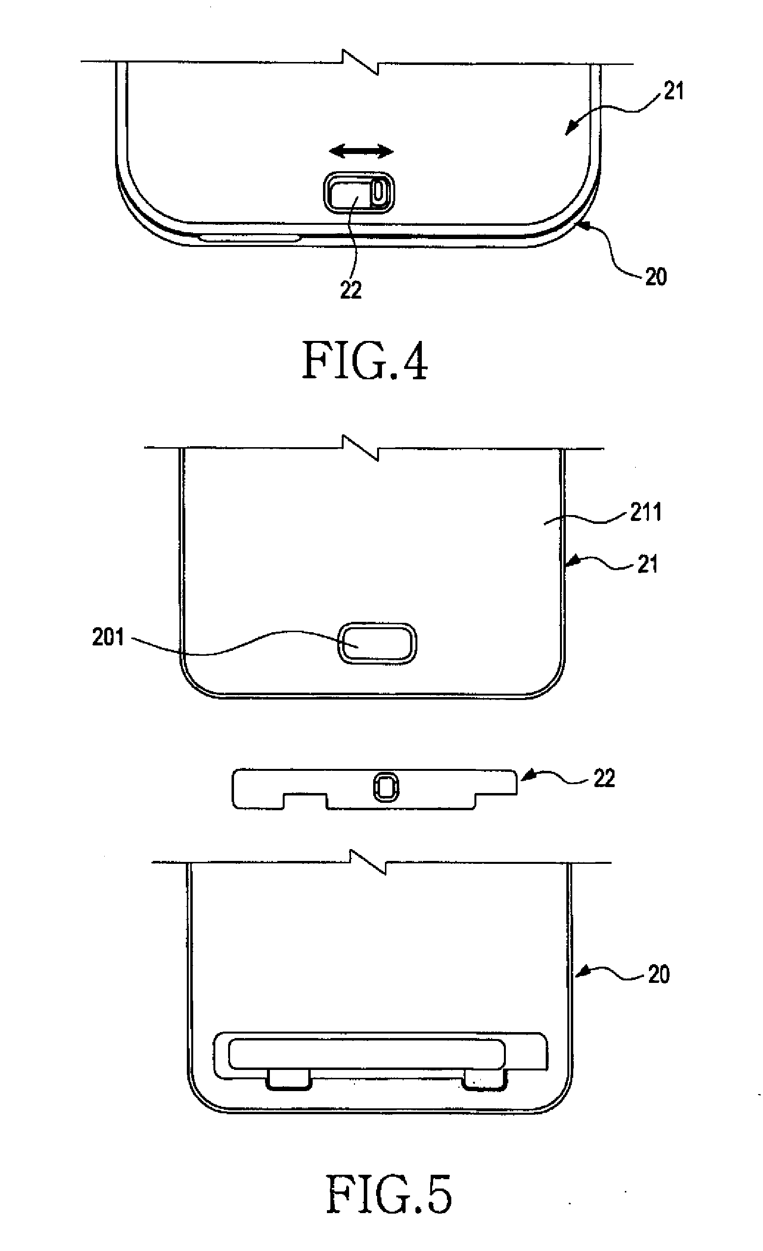
[0032]Referring to FIGS. 4 and 5, the locking device according to the embodiment of the present invention includes a body 20, a cover 21, and a locker 22 for allowing the cover 21 to be attached to or detached from the body 20, wherein the inventive locking device is adapted to conceal the locked position and the locking-released position of the cover 21 within the interior of the body 20 in such a manner that the positions are not exposed to the outside. In addition, the locking device is arranged between the inner side of the body 20 and the inner side of the cover 21, which allows its locking position not to be exposed to the external environment, so that the locking device can be protected from the external ...


PUM


Abstract

A locking device for a portable terminal includes a body; a battery cover; and a locking unit for allowing the battery cover to be selectively attached or detached from the bottom of the body, wherein a locked or locking-released position of the battery cover provided by the locking unit is located to be concealed within the interior of the body, so that the locked or locking-released position is not exposed to the outside.

Description

CLAIM OF PRIORITY[0001]This application claims the priority under 35 U.S.C. §119(a) of an application entitled “Cover Locking Device For Portable Terminal” filed in the Korean Intellectual Property Office on Nov. 12, 2010 and assigned Serial No. 10-2010-0112437, the contents of which are hereby incorporated by reference.BACKGROUND OF THE INVENTION[0002]1. Field of the Invention[0003]The present invention relates to a portable terminal including a cellular phone, a smart phone, a PMP, an MP3 player, a web pad, a tablet PC, or the like, in particular to a cover locking device, and more particularly to a battery cover locking device for such a portable terminal.[0004]2. Description of the Related Art[0005]In general, a portable terminal including a cellular phone, a smart phone or the like is provided with a battery power supply that is configured to be detachable from or embedded in the body of such a portable terminal for the purpose of recharging. In addition, a battery cover is det...

Claims


Application Information

Patent Timeline
IPC IPC(8): B65D45/00H04M1/02H05K5/03
CPCE05B65/0067E05C1/04E05C9/1825E05C9/1808H04M1/0262
Inventor KIM, JAE-SHIKJUNG, WOOK-DAMKWON, TAEK-SOO
Owner SAMSUNG ELECTRONICS CO LTD
Why Eureka
Try Eureka